| « Back: NB-IoT Node | HOME |
|---|
- Arduino
- Bootloader
- Burning sketches with an external programmer without the need of a bootloader.
- The default bootloader on our SODAQ Mbili ATMEGA1284P board
- Custom bootloaders to flash sketch from sources other than the USB serial
- Software resetting the arduino:
- Using a JUMPER, doing Over The Air programming using ubee module
- Other sources
- Similar topics about this issue
Every Arduino board is easily programmed with the Arduino IDE. You simply connect it to the computer USB and press "upload" to start the process that transfers your sketch into the Flash memory of the microcontroller. Now here's how all this works.
sketch: your piece of code that you wrote in the arduino IDE.
The little piece of code that makes it possible to transfer a sketch to the board is called the 'bootloader'. This bootloader is executed at every reset of the microcontroller and will look for a connection on the serial/USB port to upload a sketch to the board. When it doesn't detect a connection it will decide to pass on execution to the code of your sketch.
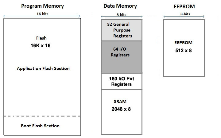
This bootloader can be found in an area of the bootloader that can't be reprogrammed as you would with a regular sketch and has been designed like that on purpose.
The bootloader comes preprogrammed on the microcontrollers of Arduino boards.
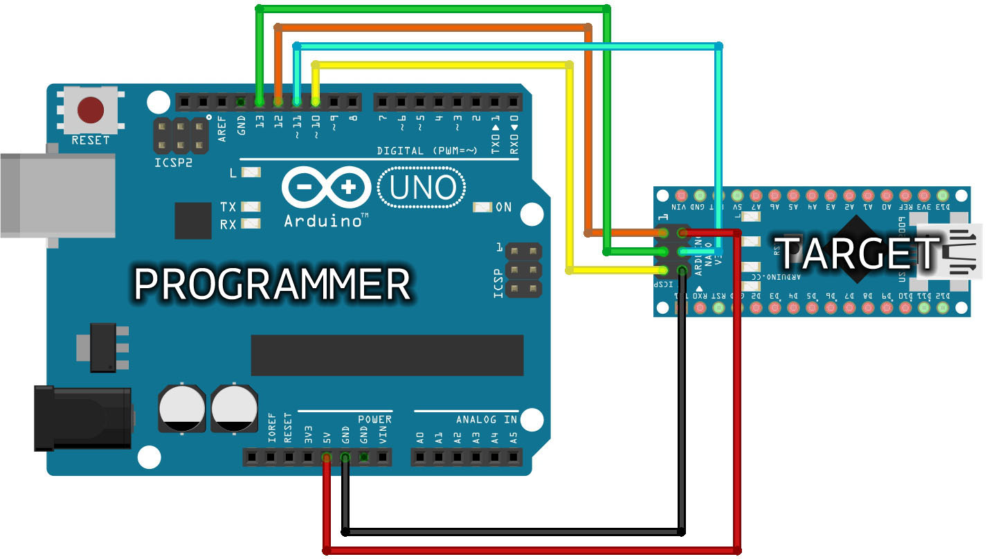
To burn the bootloader onto an Arduino board you can't simply do it the same way you would do with a regular sketch. To burn a bootloader you need a programmer. A programmer is an external Arduino device that will be an 'in-between' to your target; pc -> programmer -> target.
The programmer can be an ATmega, 32U4, ATtiny. or any other AVR-ISP/USBtinyISP.
A bootloader burned once will be able to load sketches from that point on and will not require a new burn.
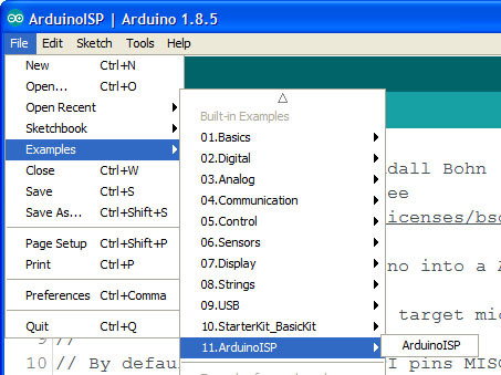
- The device used as programmer will require a specific sketch which can be found under Examples > 11.ArduinoIDP > ArduinoISP and should be uploaded as you would do with a regular sketch.
make sure to select the correct board type (eg. SODAQ Mbili...) and port (eg. COM14) of your programmer.
The programming process happens over 3 SPI lines (MISO, MOSI and SCK)
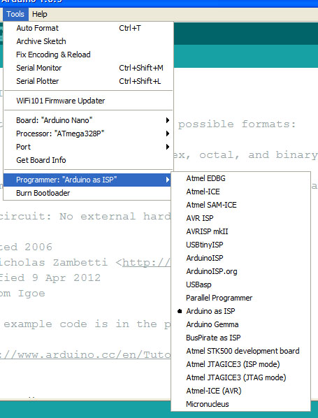
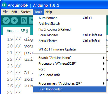
- Select the 'Arduino as ISP¨in the Tools>Programmer menu.
make sure to select the correct board type (eg. SODAQ Mbili...) of your target board.
- After making sure the previous steps are done correctly you can 'burn the bootloader' under the tools menu.
This way doesn't require any other devices, just a custom connector:
This method will only works on computers with a parallel port!
Not aplicable in our project!
By using an external programmer you can burn sketches to the Arduino board without a bootloader. This allows the use of the full program space (flash) of the chip.
This can be done by choosing 'Upload using Programmer' instead of the usual 'Upload' under the tools menu.
Make sure you set your programmer under tools > Programmer > (Arduino as ISP)
This bootloader is based off of optiboot and will be installed by default on our board. (https://github.com/SodaqMoja/optiboot.git)
Our board is a SODAQ Mbili 1284p 16MHz using Optiboot at 57600 baud.
More information can be found here: https://github.com/SodaqMoja/HardwareMbili
We can also decide to burn a custom bootloader in the device to add more functionality. The functionality we are searching for is being able to flash a sketch from SD card and boot into that. The running sketch will be able to get a new update using nbiot and write it to the SD card.
This is a dual bootloader which allows you to flash from USB or from SD card. As the documentation explains:
I can simply drag a .hex file to an SD card, insert it in an SD shield,
and field-upgrade my boards without additional hardware. At the same time,
I can connect the serial port and start developping with the normal Arduino
IDE.
and:
To run the upgrade, simply insert the SD card with the .hex file into
your Arduino, power on, and press the reset button, after a while, the new
sketch should start. Power down, and remove the SD card to prevent a reflash
on next power up. Thats it.
It is a field-upgrade where you need to be physicly present to manually insert and remove the SD card in order to perform the update.
Another minor issue is that the only supported SD cards are FAT16 formatted cards up to 2GB in size (no SDHC yet) (NO FAT32)
supports atmega1280, support for atmega1284p is unknown.
source: https://github.com/thseiler/embedded/tree/master/avr/2boots
This is an outdated(2012) project with 0 documentation. From reading the description we know that it is a SD card bootloader for atmega processors.
Checking the files we can assume it supports FAT32 (pff.c)
Looking at the makefile we can find the following definitions:
MCU_TARGET  = atmega328p	# Target device to be used (32K or lager)
BOOT_ADR    = 0x7000	# Boot loader start address [byte]
F_CPU       =16000000	# CPU clock frequency [Hz]
Which we could possible change to be this:
MCU_TARGET = atmega1284p
BOOT_ADDR = 0x1fc00
F_CPU = 16000000
But burning this outdated piece of software to our device poses a serious risk of bricking it.
bricking: the process of making a device unresponsive by burning the wrong fuses.
source: https://github.com/osbock/avr_boot
This is another project with 0 documentation. This project started out as a copy of the previous project (osbock/avr_boot), extra features got added later (in 2012).
Again: burning this outdated piece of software to our device poses a serious risk of bricking it.
source: https://github.com/mharizanov/avr_boot
This is not a bootloader but rather a sketch which has the required 'SD flashing' ability to program another device.
One device will act as a programmer and will look for a "program2.hex" on the SD card and flash the other device.
source: https://baldwisdom.com/bootdrive/
This is an I2C bootloader for Arduino. It's designed to reflash the ATmega328P with code residing in an external memory or another I2C device.
This project only supports the atmega328p and trying to make it work for ATmega1284P would not only be very time consuming but poses again a serious risk of bricking it.
source: https://github.com/mihaigalos/miniboot
An SD card bootloader for atmega processors. It will work with any ATMega and works with SD cards of the type FAT12,FAT16 and FAT32. This bootloader will check for a file "FIRMWARE.BIN" on the SD card and flash it nearly instantly. Our mbili board can be found under the supported microcontrollers and the project has been confirmed to work on a ATmega1284P.
- SD card flashing is possible after having burned this bootloader but the device will lose the ability to flash from USB serial!
- Does not perform a CRC check or versioning with EEPROM so this might be an option to consider.
- Does not get stuck in a bootloop
According to the steps under put-your-sketch-on-sd-card it has a step 'reset it' after inserting the SD card. It is unclear if having the sketch that is running jump to address 0 (the bootloader) is enough to make this happen. A jumper cable from a pinout to the reset might be required to make this possible.
source: https://github.com/zevero/avr_boot
gh-pages branch: https://github.com/zevero/avr_boot/tree/gh-page
Because all projects listed above require you to reset the arduino and it is required to be able to reset remotely without physical contact we'll need a way to reset it by software. One way to do this would be by connecting a jumper cable from a pinout to the reset, but this is higly discouraged by the arduino developers. Another way is to create a function that points to 0, while it might work, it is also highly discouraged by the arduino developers. Maybe the best way is to use a watchdog timer, the timer would be set to a very low value and an infinite while would be run after that. The watchdog timer will cause the arduino to reset after this. Doing this is pretty risky though as it might cause an infinite reset bootloop, the used bootloader will be required to have code to stop the watchdog timer very early on. (zevero/avr_boot contains this code)
source: http://forum.arduino.cc/index.php?topic=12874.msg96641#msg96641
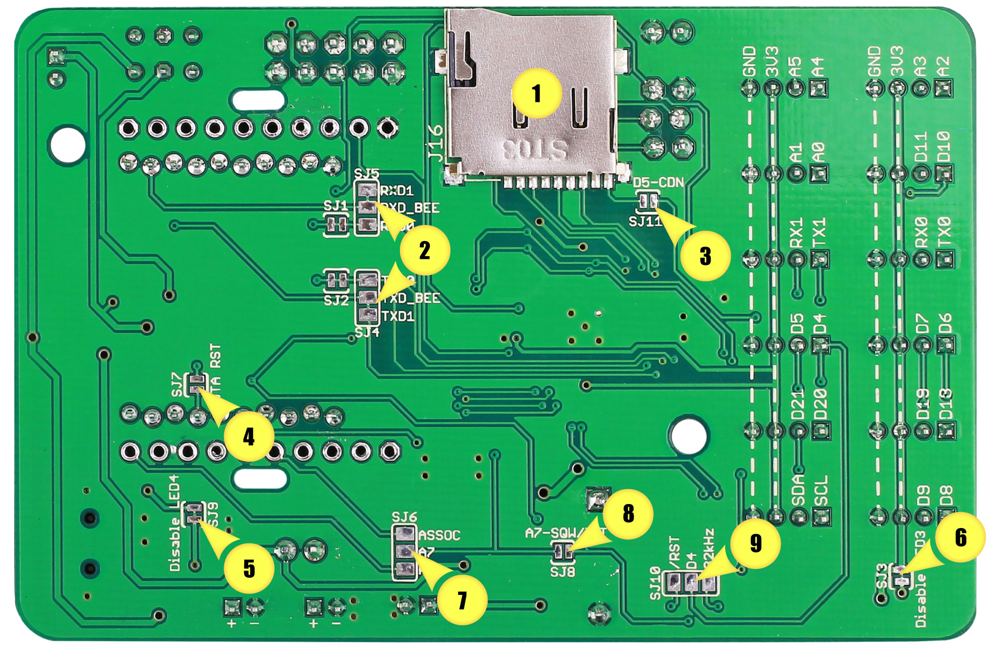
- (2) Can be used to connect the Bee socket to Serial instead of the default Serial1.
- (3) Can be used to enable the card detect functionality of the MicroSD card slot.
- (4) Can be used to allow for ‘over the air programming’ through a Bee module. This requires that the Bee socket is connected to Serial using Jumper (2).
- (5) Can be used to disconnect the Charge indicator LED to minimise power consumption.
- (6) Can be used to disconnect the Switched Grove LED to minimise power consumption.
- (7) Allows the connection of either the ASSOC pin of a Bee module or the Ring Indicator line of the GPRSBee to an I/O pin.
- (8) Allows the RTC to be used as an interrupt device.
- (9) Allows the RTC to be used as a 32kHz clock source.
0 projects can be found using this feature.
- There is also very little to no documentation about Firmware Over The Air (FOTA) programming using the SODAQ Ubee SARA N211 FOTA
- It is also unknown how big the memory size in the SARA N2 module is, the update package is 26Kb.
- FOTA will require the configuration of CoAp and a CoAp enabled server.
- It will require soldering over jumper pads 2 and 4.
http://learn.sodaq.com/Boards/Mbili/
https://www.arduino.cc/en/Hacking/Bootloader
https://www.arduino.cc/en/tutorial/arduinoISP
https://www.arduino.cc/en/Hacking/Programmer
https://www.arduino.cc/en/Hacking/ParallelProgrammer
https://forum.arduino.cc/index.php?topic=169988.0
https://forum.arduino.cc/index.php?topic=534935.0
http://dangerousprototypes.com/blog/2012/02/22/bootdrive-load-arduino-sketches-from-a-sd-card/
https://arduino.stackexchange.com/questions/19489/load-arduino-flash-code-from-sd-card
https://arduino.stackexchange.com/questions/45706/arduino-self-programming/45710#45710
less similar: https://randomnerdtutorials.com/esp32-over-the-air-ota-programming/
| « Back: NB-IoT Node | HOME |
|---|
