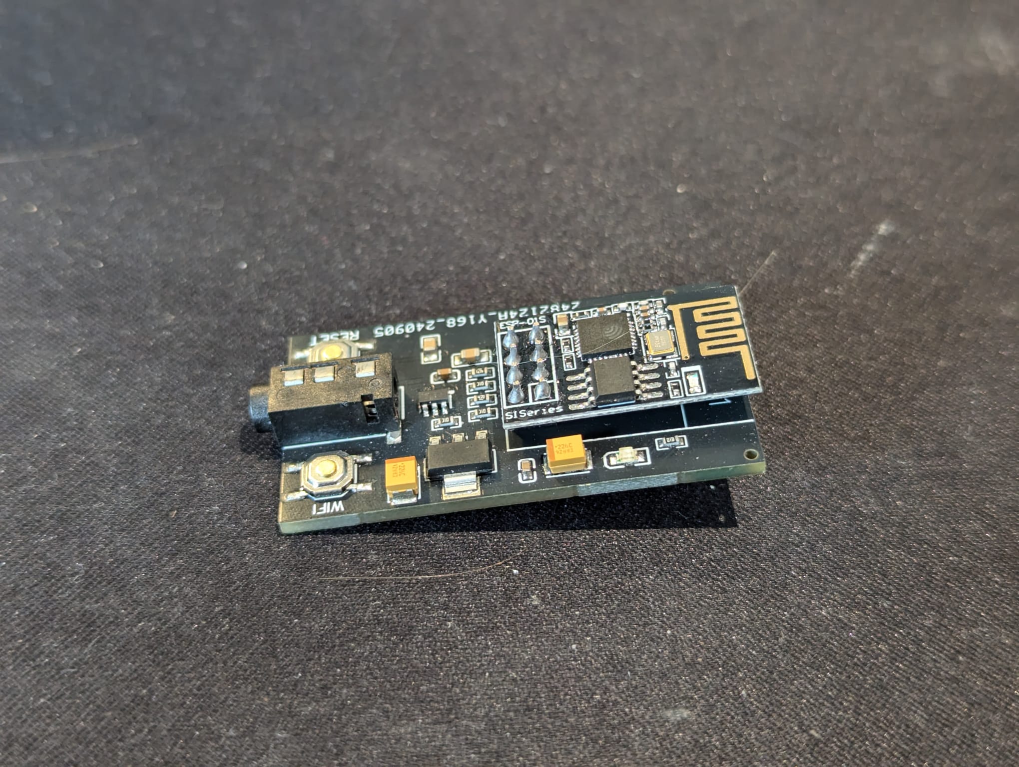
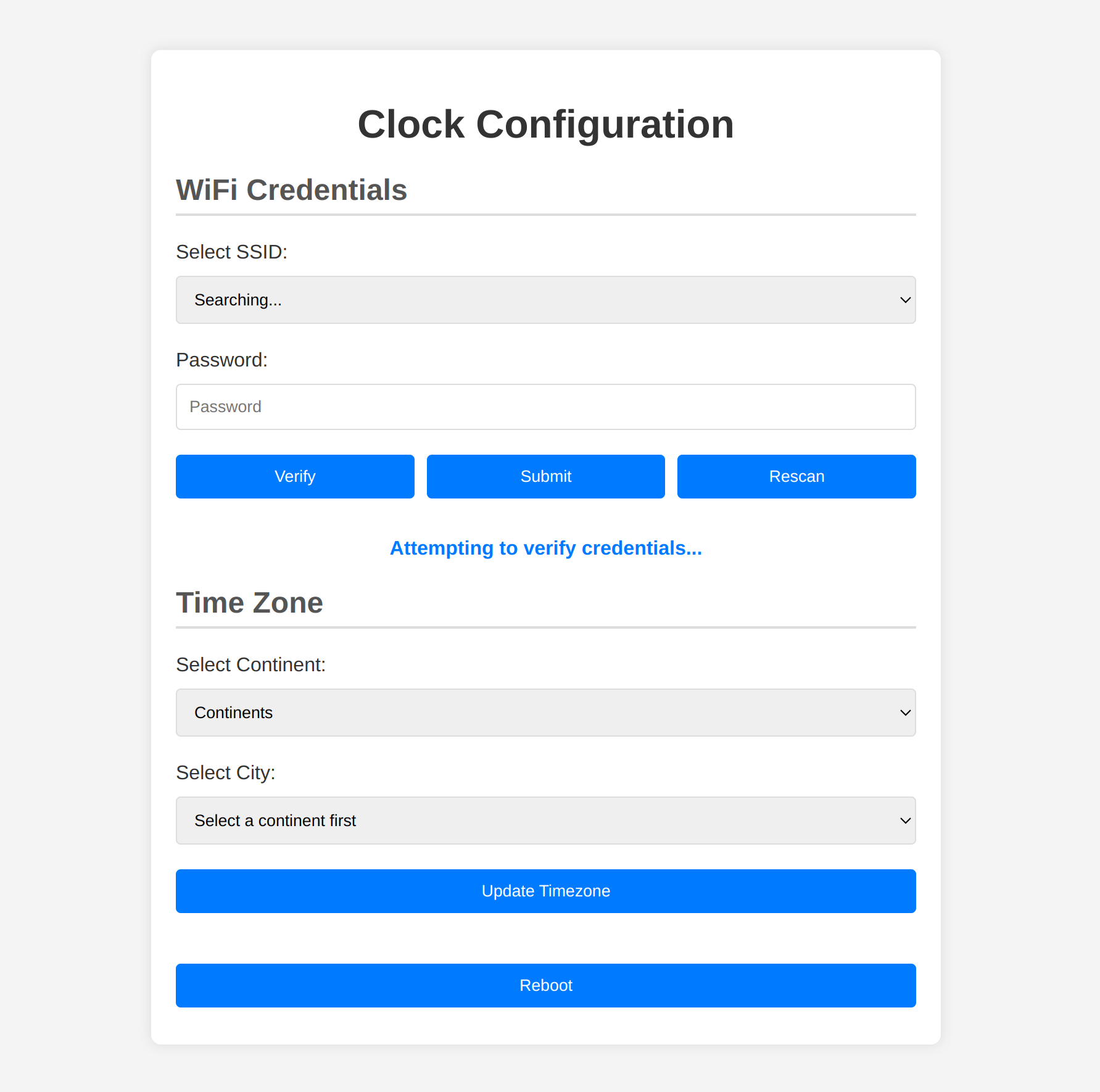
A NTP-based time module, built for nixie tube clocks. The module implements a NMEA time string protocol to set time through a 3.5mm jack, and provides a consumer oriented web interface to set wifi credentials and set time zone. The module is daylight-saving-friendly, allowing a user to configure their timezone by city, and retains configuration through power cycles
The project is based on an esp8266 - specifically an esp01S. The PCB is bespoke - the diagram can be found here --url--. The module is designed such that a standard esp8266 can be used in place - at the cost of some extra wiring.
| The module | Early UI |
|---|---|
 |
 |
The processor - An esp01S was chosen for its onboard wifi, small form factor, and shocking cost - 65p. Previously iterations of this repository are built for esp32 which provides more computing-power, however these chips are more expensive and carry a much larger form factor. These can be surface-mounted to a PCB at a cost, but an esp01S was used to minimise costs. This performace decrease is visible at times, specifically when serving large html from the flash. Later renditions may return to the esp32 as this project was originally designed for one.
The PCB - The PCB was specifically designed for this project. It features a voltage regulator to protect the esp as the nixie clocks work on a 5v logic, as well as a 4 pin headphone jack - this will be spoken about in its own section. The pcb has a header compatible with all standard esp01, cutting costs as no non-standard surface-mount components are needed. The PCB is available from --url-- at a cost of circa £4 for minimum order quantity.
The headphone jack - To those familiar with the esp, it may be obvious that there is no usb jack to write the sketch to the processor. The clocks in question expect the NMEA time string over serial transmission at 9600 BAUD through a 3 pin jack. Instead, a 4 pin jack is used here which allows the sketch to be uploaded via a serial writer through the headphone jack, as well as serving the requirements of the three pin jack when writing the NMEA string back to the clock. This saves space and costs as no second usb jack is required - a feature that would only ever be used when first uploading the code to the device
Async webserver - Most of the configuration is accessed through a web interface, hosted by the esp on its own access point. This allows a range of functions to be easily handled through any web browser, which provides a resilient and friendly interface.
Buttons - To configure the wifi setup and time zone, a button is pressed at launch to put the device into configuration mode. This iteration of the PCB/project has reused the already-present EN button which you will find on every microprocessor. Traditionally this button is used to put the device into write mode, to upload a new sketch - and outside of this the button is left unused. Within this rendition, the button is used to enter wifi mode as well which reduces costs and complexity of adding a second button, and also increases the ease of reproducing this repository yourself as. In its current form, the PCB can be reproduced with a dev board like this, with a 3.5mm jack soldered directly to its tx,5v and ground, as the EN button is already present.
TODO