-
Notifications
You must be signed in to change notification settings - Fork 2
Writing firmware
It is strongly recommended to know the basics of SubModules concept, before reading this topic.
We have 4 relays board for Arduino and we want to create new Hapacnuino 4 relay device, that will work with Hapcan system.
In main ino file, first of all You want to include all required libraries.
#include "Arduino.h"
#include <SPI.h>
#include <EEPROM.h>
#include <mcp_can.h>
#include <OnixartsIO.h>
#include <OnixartsTaskManager.h>
#include "HapcanDevice.h"
#include "SubModules\HapcanRelay\HapcanRelay.h"
Next, declare hapcanDevice, and callback functions that will handle ExecuteInstruction and StatusRequest events.
using namespace Onixarts::HomeAutomationCore;
using namespace Onixarts::Tools;

Hapcan::HapcanDevice hapcanDevice;

void ExecuteInstruction(Hapcan::InstructionStruct& exec, Hapcan::HapcanMessage& message);
void OnStatusRequest(byte requestType, bool isAnswer);
Now we declare our 4 HapcanRelay SubModules.
Hapcan::SubModule::HapcanRelay::Module out1(hapcanDevice, 1, PIN7, 0x00);
Hapcan::SubModule::HapcanRelay::Module out2(hapcanDevice, 2, PIN6, 0x00);
Hapcan::SubModule::HapcanRelay::Module out3(hapcanDevice, 3, PIN5, 0x00);
Hapcan::SubModule::HapcanRelay::Module out4(hapcanDevice, 4, PIN4, 0x00);
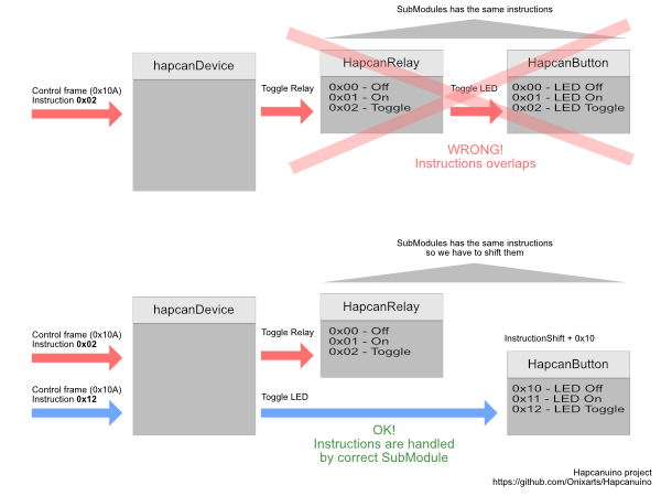
In each output constructor pass main hapcanDevice object, channel (must be unique), outputPin and instructionShift parameter (0x00 here). The last parameter is required, when
there are other SubModules defined to shift the default instruction parameter, so they won't overlap each other. For example Hapcan's relay has 3 instructions:
- Off (0x00)
- On (0x01)
- Toggle (0x02)
If You add another type of SubModule which also has instruction started with 0x00 it will overlap the HapcanRelay instruction. That will cause problems. In this case when declaring another
SubModule You can shift all the instructions, for example:
Hapcan::SubModule::HapcanButton::Module button1(hapcanDevice, 1, 0x10);will shift all instructions of the HapcanButton SubModule to value of 0x10. So instead of calling instruction 0x02 You should call instruction 0x12. 0x02 will call HapcanRelay instruction 0x02 (Toggle).

In setup() function call Init() on each SubModule. It will setup IO according to constructor definition.
void setup()
{
    Serial.begin(115200);
    Serial.println("Hapcanuino device starting...");

    hapcanDevice.Begin();

    hapcanDevice.SetExecuteInstructionDelegate(ExecuteInstruction);
    hapcanDevice.SetStatusRequestDelegate(OnStatusRequest);

    // submodules
    out1.Init();
    out2.Init();
    out3.Init();
    out4.Init();
}
Loop() function is similar. We call Update() method on each SubModule.
void loop()
{
    hapcanDevice.Update();

    out1.Update();
    out2.Update();
    out3.Update();
    out4.Update();
}
Events implementation is very similar too.
void ExecuteInstruction(Hapcan::InstructionStruct& exec, Hapcan::HapcanMessage& message)
{
    out1.ExecuteInstruction(exec, message);
    out2.ExecuteInstruction(exec, message);
    out3.ExecuteInstruction(exec, message);
    out4.ExecuteInstruction(exec, message);
}

void OnStatusRequest(byte requestType, bool isAnswer)
{
    out1.SendStatus(isAnswer);
    out2.SendStatus(isAnswer);
    out3.SendStatus(isAnswer);
    out4.SendStatus(isAnswer);
}
You can analyse instruction, params here by writing ifs, switch-case etc but it is much clearer to redirect this job to the SubModules. If instruction match these defines for HapcanRelay
and correct channel is present in params the output will react for this instruction and also automatic message will be send to the Hapcan BUS. You don't need to worry about this.
As You can see above, the code is repeated for each SubModule. This leads to the obvious solution.. more automation :).
You can write derived class, inherit from special HapcanDeviceSubModuleHost class, which inherits from HapcanDevice. It will automate all this repeated tasks.
class My4OutputRelayDevice : public Hapcan::HapcanDeviceSubModuleHost<4>
{
	// submodules declaration
	Hapcan::SubModule::HapcanRelay::Module out1;
	Hapcan::SubModule::HapcanRelay::Module out2;
	Hapcan::SubModule::HapcanRelay::Module out3;
    Hapcan::SubModule::HapcanRelay::Module out4;

public:
	My4OutputRelayDevice()
		: out1(*this, 1, PIN7, 0x00)
		, out2(*this, 2, PIN6, 0x00)
		, out3(*this, 3, PIN5, 0x00)
        , out4(*this, 4, PIN4, 0x00)
	{
        // add SubModules to the host
		m_subModules[0] = &out1;
		m_subModules[1] = &out2;
		m_subModules[2] = &out3;
		m_subModules[3] = &out4;
	}
};
It is pretty clear, right? One thing you should care about is to define valid number of SubModules in class definition HapcanDeviceSubModuleHost<4> - we have 4 SubModules here. If You want more or less, make sure
You put valid number here.
The setup() and loop() functions become even smaller now :).
// declare our new device object
My4OutputRelayDevice hapcanDevice;

void setup()
{
	Serial.begin(115200);
	Serial.println("Hapcanuino device starting...");

	hapcanDevice.Begin();
}

void loop()
{
	hapcanDevice.Update();
}
And it is all You have to do to run 4 channel output relay device. Of course there is nothing mentioned about loading configuration from EEPROM for now. It will be described later.