-
-
This article explains software architecture by analysing REAL architecture diagrams. The diagrams are from a google images search.
Google is a good place to start exploring a subject. So I did a search on the topic Software Architecture . Because I didn't want to read to much definitions I switched to the image search. You can see the result of the search in figure 1 .
Please do the search yourself and browse trough several pages. You will see lots of diagrams showing boxes and lines. So a software architect is somebody who draws BOXES and LINES. Looks like Visio or PowerPoint are the tools for a software architect.
事實上,也很難找到明確的定義,妙的是 image search 的結果五花八門;通則是 box 跟 line 組成。
The Boxes
-
The boxes and the lines are symbols for the building blocks in software architecture. A system can be divided into several SUBSYSTEMS that are represented by boxes.
-
There are many names for subsystems. Depending on the fad of the day it is important for an architect to use the proper name to distinguish his system from prior technologies.
- Module, subroutine - Basic
- Component - Component models e.g. EJB
- Class, package - Object orientation
- Service - Service oriented architecture
這跟 diagram 想要表現的粒度、或是立場的高度而有不同。
The Lines
-
Two boxes can COMMUNICATE with each other if they are connected by a line. A double sided arrow is not directed and the communication can be therefore INITIATED from both ends. If it is not a SIMPLE LINE but an arrow the communication can only be initiated in one direction towards the arrowhead. An arrow also documents a DEPENDENCY the component from ...
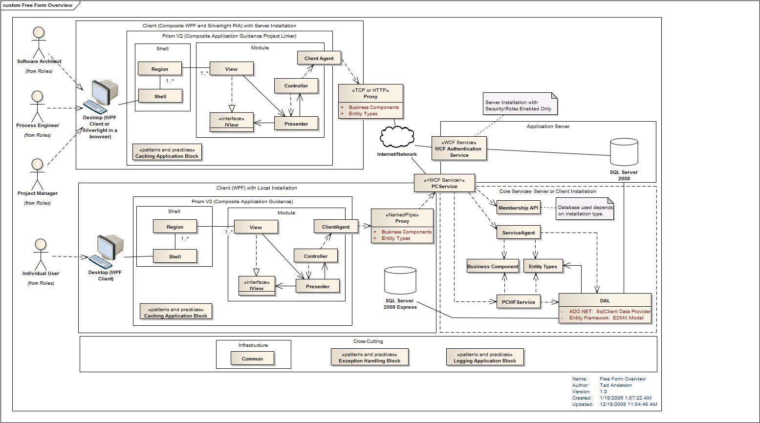
In figure 3 you can see a UML diagram with different types of lines and arrows.
Source: http://realworldsa.blogspot.com/2009/06/prism-composite-wpf-and-silverlight.html 這算是 component diagram ??
-
There are also different names for the lines:
- Connector, Adaptor - EAI, Middleware
- Interface - OO, SOA
-
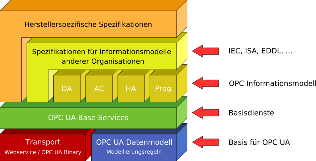
The lines are missing in some diagrams as shown in figure 4. Components in those diagrams can communicate with NEIGHBORING components or with the next component further down.
Source: http://de.academic.ru/dic.nsf/dewiki/1036788 什麼工具可以畫這種圖??
Layers of Abstractions
-
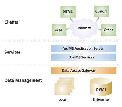
There are more architectural elements than boxes and lines. In figure 5 the diagram is structured into three layers by dotted lines. Each layer is an ABSTRACTION OF FUNCTIONALITY. The layer on the bottom offers data management functionality to the services layer. And the services layer offers functionality to several clients on the Internet. Each layer is build onto the functionality of the next layer down the stack.
Infrastructure Components and Services
-
Figure 6 displays a multi-tier architecture like the ones we have already seen. But to the left and to the right we have vertically aligned boxes that EXTEND OVER ALL LAYERS. These vertical boxes are represent CROSS CUTTING CONCERNS like infrastructure services that can be used in every component of the system.
Source: http://www.rgoarchitects.com/nblog/CategoryView,category,SPAMMED%2BProcess.aspx
Pipelines
-
In some architecture diagrams you can see a series of boxes connected with each other like a ONE WAY STREET.
Onion Diagrams
-
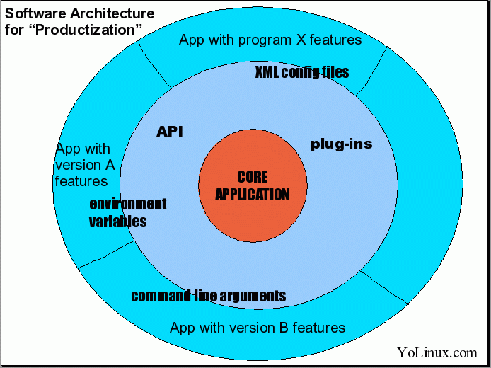
In figure 9 you can see an onion diagram. It is an other variation of a multi layered architecture. The layers are placed like onion rings around a core. The core is really tiny compared to the outer rings. This diagram is used if the core or kernel of a system is much smaller than the layers on top of it.
Source: http://www.yolinux.com/TUTORIALS/SoftwareArchitecture-Productization.html
Standards for Architecture Diagrams
-
There are a lot of initiatives that have standardized a language for the description of software architecture. The table below lists some ARCHITECTURE DESCRIPTION LANGUAGES.
- ACME - Carnegie Mellon University
- AADL - Society of Automotive Engineers
- Darwin - Imperial College London
Source: http://www.isr.uci.edu/projects/xarchuci/guide.html
感覺很古老,後來並沒有被廣為採用?
UML Diagrams
-
A lot of architecture diagrams are drawn in FREE STYLE. But you can also use an UML PACKAGE DIAGRAMS to describe an architecture visually as shown in figure 11.
Source: http://www.devx.com/enterprise/article/28296/1954
用 package diagram 來表現似乎太細了? 用 component diagram 比較合適?
Summary
- Software architecture diagrams are showing boxes and lines. And they have architectural elements like abstraction layers in common. But there is NO UNIFIED NOTATION for architectural diagrams. You can find diagrams in all styles from a hand written sketch to a glossy diagram for a marketing brochure.
-
-
What are the best ways to diagram software architecture? - Quora
Thomas Owens
-
The high level approach that I generally take when documenting architectures (or even more detailed, lower level designs) is:
-
Identify the DESIGN STAKEHOLDERS. The engineering / development team is one stakeholders. Your testing / quality assurance team, IT infrastructure team, project management, and maybe support staff may also be stakeholders of the system and interested in VARIOUS ASPECTS of the design.
-
Identify the AREAS OF CONCERN in your system. If your system has a database, one viewpoint is the database structure. If you have a distributed system, then the system administrators or customer service staff may be interested in where components are installed. If you have a public interface, then external developers are interested in what that interface is - file formats, data formats, etc. If you have many complex algorithms, then the algorithm designers/maintainers are interested in the workflows and algorithm steps.
Each VIEWPOINT that you identify is a specific set of concerns.
-
For each viewpoint that you have, choose an appropriate REPRESENTATION. For your database viewpoint, perhaps ENTITY-RELATIONSHIP DIAGRAMS and a data dictionary may be useful. For public interfaces, XML Schema Documents or API documentation can be included as part of your documentation. For complex algorithms, consider UML activity or interaction overview diagrams.
When you choose a notation, I prefer well-known and well-defined notations so that I don't need to explain my notation to someone else and can simply point them to existing reference material if they don't know the symbols used.
-
Add textual descriptions and rational around the diagrams. Explain not only what the architectural decisions that you made were, but what drove you to make those DECISIONS.
額外補充 "為什麼要這樣設計",這是圖形本身無法表現的。
-
-
Architectural frameworks, such as the Zachman Framework, The Open Group Architectural Framework, the Department of Defense Architectural Framework, and other architectural frameworks help by defining essential viewpoints and views that are generally applicable. ??
-
Ultimately, "the best" documentation is that which meets the needs of the stakeholders. Identifying who needs the information and what exactly they need is the first step.
說得真好!! 先找出 stakeholder、不同的觀點 (viewpoint) 想知道什麼? (areas of concern)、用什麼方式表現最合適? (representaiton) 補充說明為什麼要這樣設計;這滿符合 UML 的想法,不同 diagram 間是互補的。
Camilo Sanchez
-
I usually find myself using the C3 plus approach to architecture diagramming (Page on codingthearchitecture.com) #ril
PDF 裡講的是 "C4 Model",猜想 C3 plus 指的是 C3 (System Context, Container, Component) + Code (optional)。
其中 Code 可以用不同的 UML diagram 表現。
-
It gives you enough information to start discussing with the bussiness / non-tech people (Context), then move to the infrastructure / non-coding people (Container) and finally show to the technical / programming people the desired approach (Component) . This just with the 3 Cs .
-
After this you can extend the PLUS PART to whatever fits you based on your personal prefferences or in the technical needs.
- Do you need to model an entity which constantly changes states and guides the flow on your application? Do a state machine diagram.
- Do you need to show the interaction between your brand new created classes than nobody else nows? Draw a sequence diagram.
- Do you want to show how you imagine the user view of the web application? Draw it in a napking, whiteboard, paper (And the digitalize it so you dont loose it).
-
Summarizing dont let the "I must do this diagram" cages you. The diagrams are there to help you EXPLAIN HOW DO YOU THINK the architecture should be. Any diagram that helps you make thins ckear to any of the involved actors is a good diagram, even if it is just a hand drawed super duper new approach.
-
-
Software Diagrams for PowerPoint - SlideModel 感覺 PowerPoint 這類 Slides 編輯軟體就很夠用?
-
Why Do We Need Architectural Diagrams? (2019-01-19)
-
We try to create architectural diagrams (as part of the technical documentation) aiming to reflect the INTERNAL STATE of the application, but most of the time we do not do it properly. The resulting diagrams can range from very comprehensive to extremely vague. Sometimes, the diagrams are simply IRRELEVANT. I previously wrote a few tips on how to create useful architectural diagrams.
-
Even when relevant diagrams are created, we RARELY KEEP such documentation UPDATED with the feature which is being developed as part of an integrated continuous development process. In reality, the documentation is updated only from time to time, probably during some sprints (when there is time for such activity), or for a specific release.
On the other hand, most of the developers I interacted with (colleagues or students attending my Software Architecture course) are not in favor of creating and maintaining technical documentation; they consider it tedious, time-consuming, and less valuable than other work, or even unnecessary when SOURCE CODE IS ENOUGH. While there will always be exceptions, I am pretty sure when it comes to architectural diagrams things are pretty much the same in most of the projects.
雖然 "source code is enough" 的說法沒錯,但要從 code 反推出整個 overview 其實不容易。
What we do wrong and how we can improve
-
First of all, it is important to understand who are the real beneficiaries of architectural diagrams and technical documentation. The quantity and quality of the documentation should reflect the STAKEHOLDERS' NEEDS, since only this way we can create accurate and JUST ENOUGH documentation.
與 What are the best ways to diagram software architecture? - Quora 中 Thomas Owens 的想法一致,先找出 stakeholder 想知道什麼。
-
The main beneficiary should be the team (developers, test engineers, business analysts, DEVOPS, etc.) who have DIRECT INVOLVEMENT in the project. In my experience, outside of the team, there are VERY FEW stakeholders who really care about documentation. In the best case, they might be interested in one or two HIGH-LEVEL diagrams (e.g. context diagram ??, application or software component diagram) which roughly describe the structure of the system and give a high-level understanding of it.
在開發 team 之外,很少人想看文件,所以也沒必要寫;但在開發 team 之內,必要的文件還是得維護。
-
However, most of the time we fail in identifying the real beneficiaries and their real needs and try to create TOO MUCH documentation. This quickly becomes a burden to maintain and is quite soon outdated. In other cases, we just simply omit to create any kind of diagram because there is no time, no specific interest, or nobody wants to take on this responsibility.
Besides this, the AGILE MANIFESTO prescribes that teams should value working software over comprehensive documentation, which discourages cumbersome documentation processes.
兩個極端 -- 不是寫太多沒人看,就是什麼都不寫;但這中間應該取得平衡。
-
In order to find the appropriate BALANCE of the right DOCUMENTATION LEVEL, try this exercise in your team: go to ask each of your colleagues what they really need out of the technical documentation and what types of diagrams it should include. Collect their input, then brainstorm and AGREE TOGETHER on what is REALLY NECESSARY FOR THE TEAM.
There might be one or two influential stakeholders outside of the team with extra requests, and it is the responsibility of the architect to take their needs into account, as well.
Based on that, create the appropriate quantity and level of technical documentation which fulfills the stakeholders’ needs. If developers understand the real value of the documentation and have as interest in its remaining valuable, they will be encouraged to contribute and properly maintain it. In the end, everybody becomes happy. However, if they do not understand the necessity or they do not care, you can almost forget about it, since documentation becomes very difficult to maintain by a just SINGLE PERSON (THE ARCHITECT) when this must be a SHARED RESPONSIBILITY among the team members.
-
In the past, on waterfall projects, we created too much documentation derived from comprehensive enterprise architecture methodologies (I intentionally do not name any of them) or requested by some IVORY TOWER ARCHITECTS. When agile methodologies were embraced at large scale in software projects, one common, big MISUNDERSTANDING was people thinking they did not need any documentation, because working software is more important than creating comprehensive documentation.
These are the two extreme cases, of course. There is no precise methodology or scientific process to explicitly address the appropriate amount of documentation for a project. All current software architecture methodologies are pure recommendations or guidelines. Those comprehensive architectural processes followed in the past are nowadays substantially simplified to non-existence in the projects. It doesn’t mean we should create less documentation or no documentation at all, but rather be focused on creating documentation that PROVIDES REAL VALUE and at the same time does not hinder the team’s progress.
Besides that, not all documentation provides value. But that isn't the same as "all documentation provides no value." Additionally, what makes sense for one project might be less relevant for another due to a different context (e.g. economic, political, etc.), business goals, stakeholders, etc.
-
Under these circumstances, it is very difficult to get the right answer to the question: what is the appropriate amount of technical documentation (i.e. architectural diagrams)? In the end, it relates to each project and to the architect experience, and could be summarized as "IT DEPENDS." The right amount of documentation to provide value depends on what your team has decided they need.
My advice is to DECIDE TOGETHER with the team and to create just enough technical documentation, whatever that means for your team. If no documentation makes sense for your project (why not!?), that might be acceptable. Document the rationale behind this TEAMING AGREEMENT and make it transparent for all stakeholders. If there are two or three diagrams of real interest, then make sure they are updated, consistent and always reflect the state of the system. Do not focus on anything else which might not bring any value.
But … what do we need architectural diagrams for?
-
The architectural diagrams in particular and the documentation, in general, should be primarily used for collaboration, communication, vision and guidance inside the team and across teams. It must also include the significant DESIGN DECISIONS in the project (taken at a certain moment of time), but nothing more.
-
Architectural diagrams should help everybody to see the BIG PICTURE and to understand the SURROUNDINGS. In my opinion, this should be the fundamental reason behind creating and maintaining the architectural diagrams.
For example, CONTEXT DIAGRAMS perfectly fulfill such a need and provide a great level of detail about SYSTEM BOUNDARIES, seeing the big picture. It helps the team to have a common understanding and ease communication across different stakeholders. I attended many meetings when such a context diagram, presented on the big screen, saved a lot of questions and removed the uncertainties about the high-level system architecture.
-
However, we often we try to create comprehensive documentation to reflect the internal state of the system. This can take the form of state diagrams, activity diagrams, class diagrams, entity diagrams, concurrency diagrams, etc. But these quickly become out of date, unless they are AUTOMATICALLY GENERATED out of the source code by some “magic” tools.
需要討論細節時才產生圖形,這類工具並非毫無用處。
-
What would be the purpose of creating such detailed diagrams if people do not need, read or maybe understand them? Abstract diagrams for business stakeholders are more than enough. For developers, in most of the cases, the source code (i.e. SINGLE SOURCE OF TRUTH) is what they really need in order to understand the application.
So, please stop creating diagrams for things that are SELF-EXPLANATORY in the code, too detailed, or when there is NO REAL AUDIENCE.
如果 source code 本身不是 self-explanatory,那又是另一個問題了。
-
Create meaningful, but minimal, architectural diagrams and incorporate them in the technical documentation. For the majority of applications, there are probably TWO OR THREE TYPES of such significant diagrams needed. The most common are context diagrams, application/software component diagrams, system diagrams, or deployment diagrams.
其中 component diagram 跟 deployment diagram 都可以理解,但什麼是 context diagram 跟 system diagram ??
My practical example
-
In my project I use mainly two types of diagrams:
Context diagrams
Application or software component diagrams
-
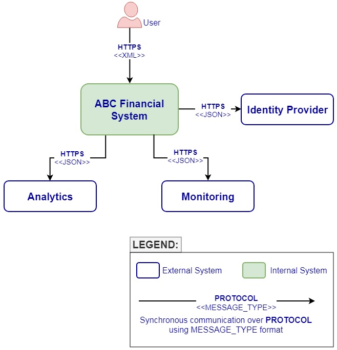
Please treat these diagrams as simple examples, showing some guidance about a REASONABLE LEVEL OF INFORMATION each diagram should provide. Information on one diagram should be RELEVANT TO THE CORRESPONDING ABSTRACTION LEVEL, but also must fulfill stakeholders needs.
In practice, it might be tempting to add more and more details to a diagram, but if they are not really useful to the beneficiaries, it leads to extra NOISE, increased maintenance and the risk of being out of date. Specific to these diagrams, including details like protocols and data format might be very handy for technical stakeholders, since they are a necessary implementation detail.
However, as also stated in the article, there is no precise methodology to explicitly describe the appropriate amount of details a diagram should include. It really depends from project to project, nevertheless, the architect must identify what is really useful for the stakeholders and create and maintain the diagrams to properly reflect that.
-
For any extra detail besides these diagrams, I could either find it in the source code or get it automatically generated by some tools (e.g. runtime view diagrams, development view diagrams, system or infrastructure view diagrams, etc).
Deployment diagram 要如何自動產生?
-
I also painted the software architecture diagram (including all application components) in our meeting room. During our stand-ups and other meetings, people talk about their tasks, statuses, and impediments while pointing to this diagram on the wall. This way, every team member, from product owner to developer, understands and sees the big picture and foresees the overall impediments and other integration challenges.
Besides that, it offers a more accurate progress status during the Sprint for the entire team, especially when the architecture is distributed and there are DEPENDENCIES BETWEEN PEOPLE.
-
I advise you to do the same for your team. Keep on increasing collaboration, communication, vision, and guidance by using just enough architectural diagrams, and stop creating them for any other reasons, especially if the team does not use them.
Manually creating and maintaining diagrams to reflect the code behavior is, in most of the cases, a waste of time. In doing so, you might be tempted to add more and more such diagrams as source code evolves, which is a dangerous trap. Rather than creating an exhausting number of diagrams, stick to TWO OR THREE which describe the system from different levels of abstractions and are really necessary for the team. Always keep them updated; this task is made easier when it does not contain too many details and it is part of the TEAM CULTURE.
-
Also, keep in mind the team should be the main beneficiary of architectural diagrams. If they do not manifest any interest, then you should probably stop creating them; it might be waste of time. We should not create architectural diagrams just “for the sake of having them,” to follow some comprehensive methodologies, or to justify our role as Architects.
最後一句 "justify our role as architects" 很酸,彷佛 architect 要能畫漂亮的架構圖才能證明它的存在 ...
-
-
The Art of Crafting Architectural Diagrams (2017-08-04) #ril
- 主要是 Component Diagram 與 Deployment Diagram,其中 component 可大可小,依圖形想要呈現的粒度而定 -- 可以是 subsystem、service、module。
- 根據 C4 Model "由宏觀到細節" 的概念 -- Context (外部看整個系統)、Container (內部分不同 application) 到 Component,其中 Context 可以用 Use Case Diagram 表現,帶出 external entity (user/system),而 Container、Component 則可以用 Component Diagram 表現。
相關:
