-
Notifications
You must be signed in to change notification settings - Fork 77
connectst7735

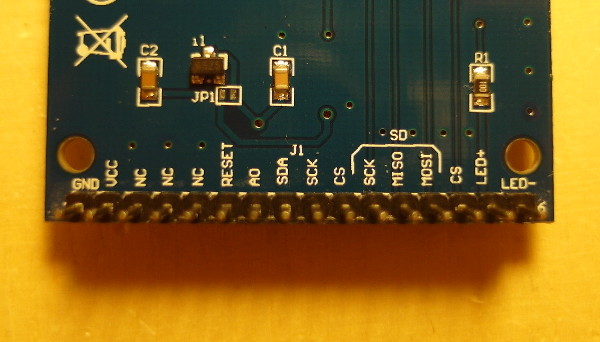
There are three important parts on this display module:
- The voltage regulator (above JP1) provides 3.3Volt to the display. This is useful if 5 Volt are applied to VCC (second pin from the left). Always ensure that jumper JP1 is open.
- There are five pins for the data transfer to the display: RESET, A0, SDA, SCK, CS. This indicates a 4-wire SPI interface (A0, SDA, SCK, CS).
- The backlight LED has two pins on the right. From the datasheet: Forward voltage of the LED is about 3.3V, current about 30mA. In this example, the LED will be powered by 5 Volt. As a result, the required resistor should have the value (5V-3.3V)/0.03A = 56 Ohm. In the picture above, the resistor is at the top left corner of the display.

The following constructor is suitable for this ST7735 display:
Ucglib_ST7735_18x128x160_SWSPI ucg(uint8_t sclk, uint8_t data, uint8_t cd, uint8_t cs, uint8_t reset);
The best method for wiring a display is to start with a table that contains the signals. The sequence should be the same as for the arguments of the constructor call:
| Constructor argument | Arduino pin number |
|---|---|
| sclk | |
| data | |
| cd | |
| cs | |
| reset |
Now the signal lines need to be matched to the display pins. This should be easy except for the "cd" argument. The cd signal (command/data) has a lot of names. Often used are: CD, DC, D/C, RS, A0. In this case, the "cd" line is named as A0 on the PCB.
Now, the display can be connected to the Arduino Uno. The table will look like this (compare picture at the top of this page):
| Constructor argument | Arduino pin number |
|---|---|
| sclk | 13 (brown) |
| data | 11 (gray) |
| cd | 9 (blue) |
| cs | 10 (green) |
| reset | 8 (white) |
With the numbers from the table, the corresponding constructor call will look like this:
Ucglib_ST7735_18x128x160_SWSPI ucg(/*sclk=*/ 13, /*data=*/ 11, /*cd=*/ 9 , /*cs=*/ 10, /*reset=*/ 8);
Here is A simple "Hello World" example:
#include <SPI.h>
#include "Ucglib.h"

Ucglib_ST7735_18x128x160_SWSPI ucg(/*sclk=*/ 13, /*data=*/ 11, /*cd=*/ 9 , /*cs=*/ 10, /*reset=*/ 8);

void setup(void) {
  delay(1000);
  ucg.begin();
  ucg.clearScreen();
}

void loop(void) {
  ucg.setFont(ucg_font_ncenR14r);
  ucg.setPrintPos(0,25);
  ucg.setColor(255, 255, 255);
  ucg.print("Hello World!");

  delay(500);
}
The hardware SPI subsystem can be used to speed up the data transfer to the display, Usually the hardware SPI is available only at specific pins of the controller. For the Arduino Uno these are pin 13 for clock and pin 11 for data. If the corresponding display lines are connected to these pins, then also the hardware SPI interface can be used:
#include <SPI.h>
#include "Ucglib.h"

Ucglib_ST7735_18x128x160_HWSPI ucg(/*cd=*/ 9 , /*cs=*/ 10, /*reset=*/ 8);

void setup(void) {
  delay(1000);
  ucg.begin();
  ucg.clearScreen();
}

void loop(void) {
  ucg.setFont(ucg_font_ncenR14r);
  ucg.setPrintPos(0,25);
  ucg.setColor(255, 255, 255);
  ucg.print("Hello World!");

  delay(500);
}