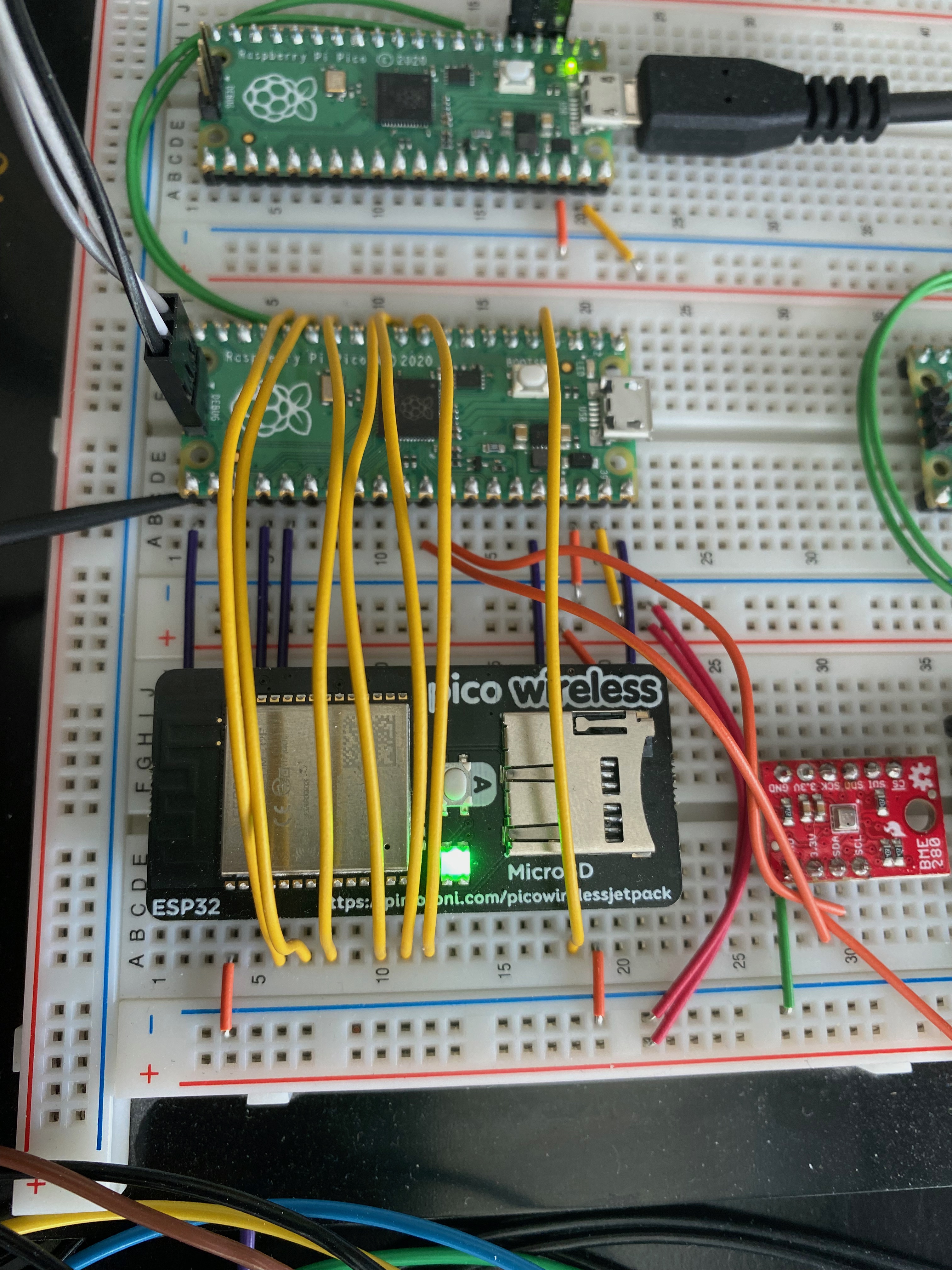
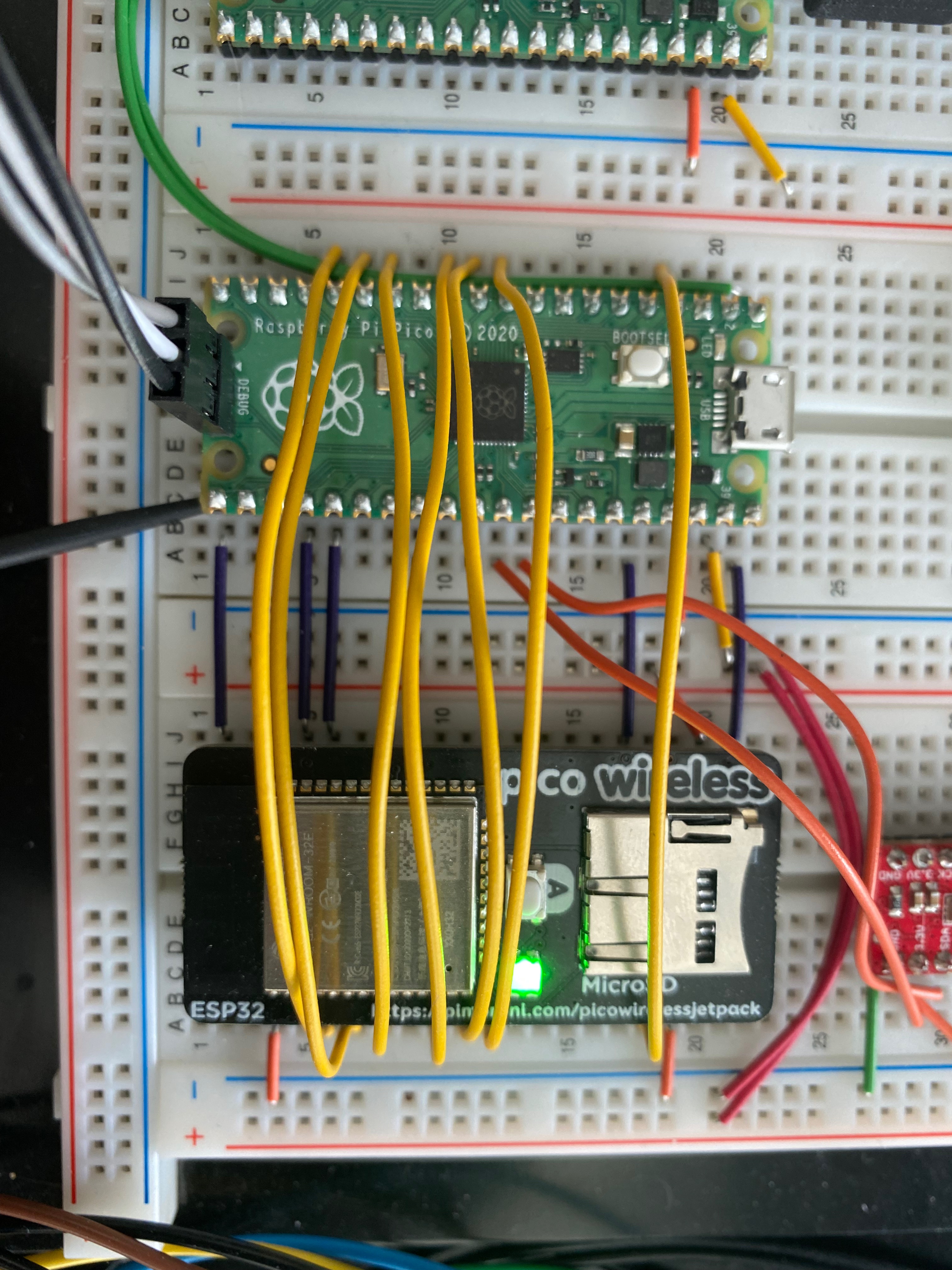
This is a proof-of-concept project that translates enough of Pimoroni's C++ code into a Rust implementation to POST to an Ambi web backend instance with live temperature, pressure and humidity values via a BME280 sensor.
This project will eventually turn into a full open source library that implements most or all of the WiFi functionality for use in any embedded Rust application.
For more details see the following article on getting started for getting your environment set up on Mac/Linux: https://reltech.substack.com/p/getting-started-with-rust-on-a-raspberry
At the time of writing, this code is heavily influenced by the Pimoroni C++ Wifi driver: https://github.com/pimoroni/pimoroni-pico/blob/main/drivers/esp32spi/
In order to run this code you need to purchase some hardware. This section provides a list of required hardware needed at minimum, and some suggested items to make your life even easier.
-
Pimoroni Pico Wireless Pack (1x)
-
BME280 temperature/pressure/humidity sensor (1x)
-
Breadboard (1x)
- Note: If you already have a medium/large breadboard, then don't worry about purchasing this specific one
-
Break Away Headers (1x)
- If you want to solder headers to the non-pre-soldered BME280 sensor board from #2 above
-
Straight 7" Jumper Wires M/M (1x)
- Helpful to have some of these on hand
-
Straight 6" Jumper Wires M/F (1x)
- Helpful to have some of these on hand
-
Saleae Logic 8 (1x)
- Note: Only needed if you'd like to participate in developing/debugging parts of this project that communicate on the SPI/I2C buses
Start with the section Pico to Pico Wiring in this article to set up using two Picos together, one as a Picoprobe (flash/debug) and the other as your embedded target.
Once properly wired, it should look similar to the following:
Pico to ESP32 WiFi
The following table lists the pin name and pin number to properly wire between a Pico board and an ESP32 WiFi. This can be done on a breadboard such as the one listed above. Note that V+/- rail means the +/- columns on the breadboard for use as +5 VDC and GND respectively.
| Pico | ESP32 WiFi | Adafuit Airlift | Breadboard |
|---|---|---|---|
| GND (Pin 3) | GND (Pin 3) | V- rail | |
| GP2 (Pin 4) | GPIO0 (Pin 4) | GP0 (Pin 10) | |
| GP7 (Pin 10) | ESP_CSn (Pin 10) | CS (Pin 7) | |
| GP8 (Pin 11) | |||
| GP9 (Pin 12) | |||
| GP10 (Pin 14) | ACK (Pin 14) | Busy (Pin 8) | |
| GP11 (Pin 15) | RESETn (Pin 15) | RSTn (Pin 9) | |
| GP12 (Pin 16) | SW_A (Pin 16) | N/A | |
| GND (Pin 18) | V- rail | ||
| VBUS (Pin 40) | VBUS (Pin 40) | ||
| VSYS (Pin 39) | VSYS (Pin 39) | VIN (Pin 1) | V+ rail |
| GND (Pin 38) | GND (Pin 38) | V- rail | |
| 3V3(OUT) (Pin 36) | 3V3 (Pin 36) | 3Vo (Pin 2) | |
| GP19 (Pin 25) | MOSI (Pin 25) | MOSI (Pin 5) | |
| GP18 (Pin 24) | SCLK (Pin 24) | SCK (Pin 4) | |
| GND (Pin 23) | V- rail | ||
| GP16 (Pin 21) | MISO (Pin 21) | MISO (Pin 5) |
BME280 to Pico
| BME280 | Pico | Breadboard |
|---|---|---|
| GND | V- rail | |
| 3.3V | 3V3(OUT) (Pin 36) | |
| SDA | I2C1 SDA (Pin 31) | |
| SCL | I2C1 SCL (Pin 32) |
-
The standard Rust tooling (cargo, rustup) which you can install from https://rustup.rs/
-
Toolchain support for the cortex-m0+ processors in the rp2040 (thumbv6m-none-eabi)
-
flip-link - this allows you to detect stack-overflows on the first core, which is the only supported target for now.
rustup target install thumbv6m-none-eabi
cargo install flip-link
cargo install probe-run
The esp32-pico-wifi repository makes use of several Git hooks to ensure that code quality standards are met and consistent. To automatically configure these hooks for your local workspace, you can run the following:
./scripts/create-git-hooksThis will create symlinks to the Git hooks, preserving any hooks that you may have already configured.
For a debug build
cargo run
For a release build
cargo run --release
To see debug output on the serial console on macOS:
minicom -D /dev/tty.usbmodem14201 -b 115200
or on Linux:
minicom -D /dev/ttyUSB0 -b 115200
Note that you'll most likely need to find the current /dev link assigned to the Pico UART for your particular machine.
Note: these instructions originate from the rp-hal project's rp2040_project_template README
To start a probe-rs debug session:
Step 1 - Download probe-rs-debugger VSCode plugin 0.4.0
Step 2 - Install probe-rs-debugger VSCode plugin
$ code --install-extension probe-rs-debugger-0.4.0.vsixStep 3 - Install probe-rs-debugger
$ cargo install --git https://github.com/probe-rs/probe-rs probe-rs-debuggerStep 4 - Open this project in VSCode
Step 5 - Launch a debug session by choosing Run>Start Debugging (or press F5)
This project is licensed under the BSD + Patent license.
Any submissions to this project (e.g. as Pull Requests) must be made available under these terms.

