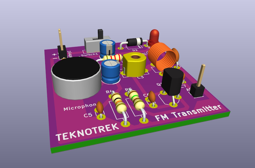
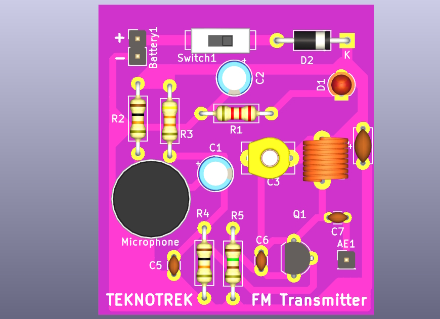
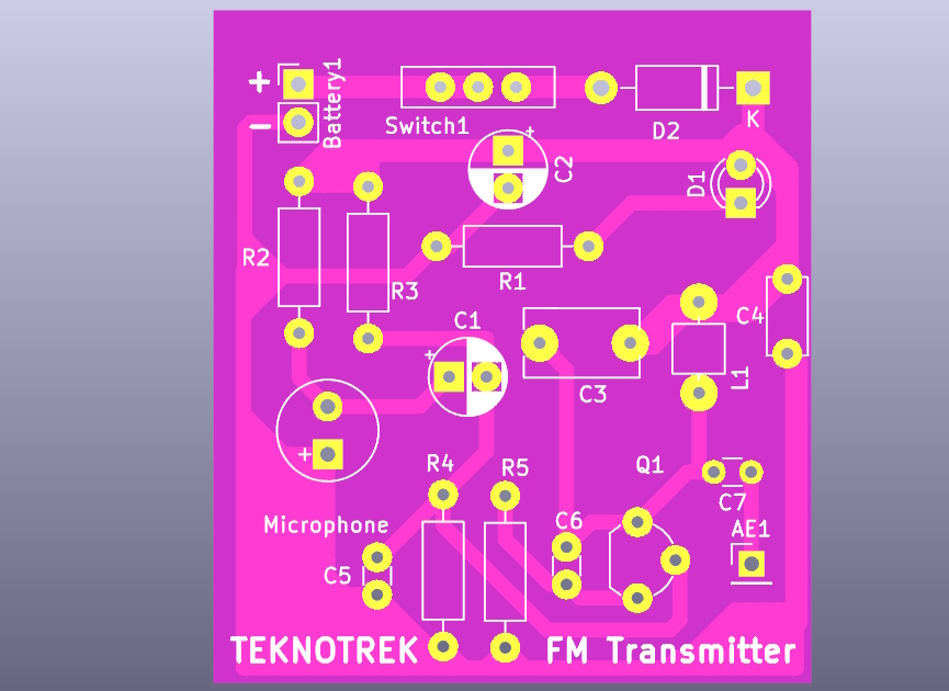
This repository contains the KiCad project files for an FM Transmitter circuit operating in the 88 MHz – 108 MHz range. The design includes both the circuit schematic and the PCB layout, with a 3D model of the assembled board.
This FM transmitter is designed to broadcast audio signals using a microphone input. It covers the standard FM radio frequency range and is powered by a 9V battery. The circuit is based on a single transistor (BC548) and includes adjustable frequency tuning through a variable capacitor (C3).
- Frequency Range: 88 MHz – 108 MHz
- Microphone input for real-time audio transmission
- LED power indicator
- Compact PCB design
- Easy to assemble
You can watch the full build process of this FM transmitter on my YouTube channel Teknotrek. Click the link below to see how the circuit is assembled, soldered, and tested:
The circuit consists of the following key components:
- Q1 (BC548): The main transistor used for signal amplification and modulation.
- C3 (0-30 pF): A variable capacitor for tuning the frequency.
- L1 (Coil): Works with C3 to set the oscillation frequency.
- Microphone: Captures the audio to be transmitted.
- Antenna: Transmits the modulated FM signal.
The PCB layout is designed to be compact, with clear labels for easy assembly. The board supports through-hole components for easier soldering.
A 3D model of the assembled PCB is included to give you a better idea of how the final product will look.
-
Clone the repository:
git clone https://github.com/TeknoTrek/fm-transmitter.git
-
Open the project in KiCad and review the schematic and PCB layout.
-
Assemble the components as per the schematic, solder them to the PCB, and tune the frequency using C3.
-
Attach a suitable antenna and power the transmitter using a 9V battery.
Let me know if you'd like to adjust any part of it!


