-
-
Notifications
You must be signed in to change notification settings - Fork 2
Hardware installation guide
- soldering iron
- flux
- soldering wire
- crafting knife
- drill/dremel tool
- 2mm and 4mm drilling bits
- small file
This guide doesn't cover this step but you can refer to iFixit guide here: https://www.ifixit.com/Guide/Nintendo+Wii+mini+Motherboard+Replacement/37774
You need to teardown whole system down to the motherboard where you'll solder first component of the kit.
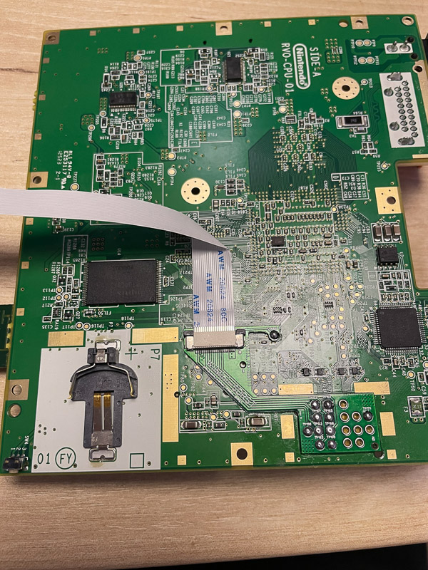
Line up hookup PCB with test points on Wii Mini motherboard. Make sure all points will make good contact with the PCB. You can use sticky tape to hold the board in place while soldering.
For better results, use proper amount of flux. It's important to use good quality soldering tip which can transfer enough heat to the motherboard. As seen in the picture, you can skip some of the points not used by this mod. It'll be easier to reverse the mod if needed.
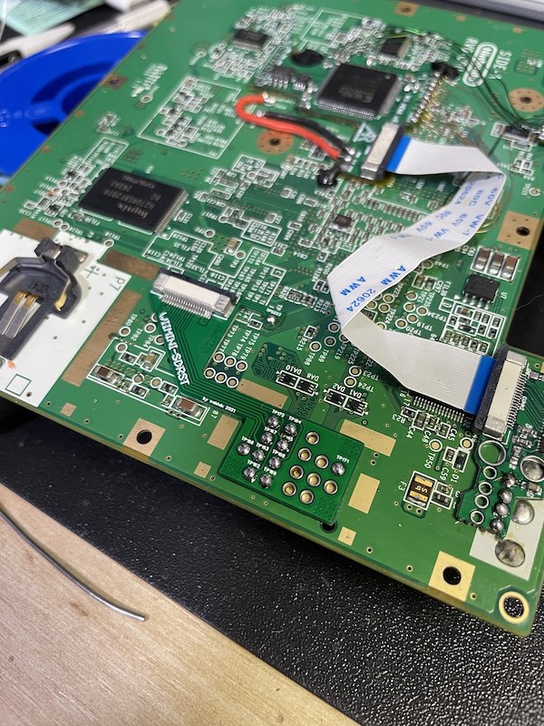
You can connect FFC cable now. Fold it as shown in the picture. Route it so that it goes under WiFi module area. Make sure the FFC is routed away from screw holes or it'll get damaged during assembly.
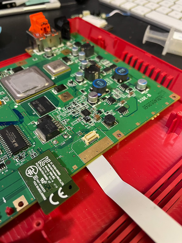
The kit comes with 2 3D printed drill guies. They're used to make clean cutout for microSD card slot and reset button. Start with either one and mount it to the screw post, note the correct orientation as shown in the photo. Do not use both attached at the same time.
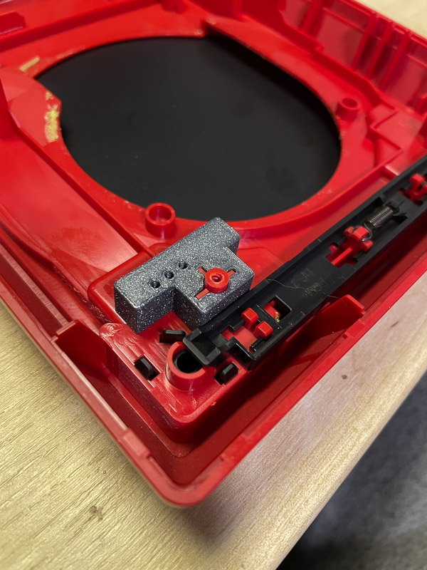
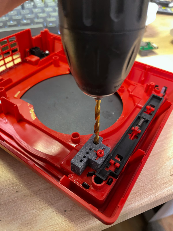
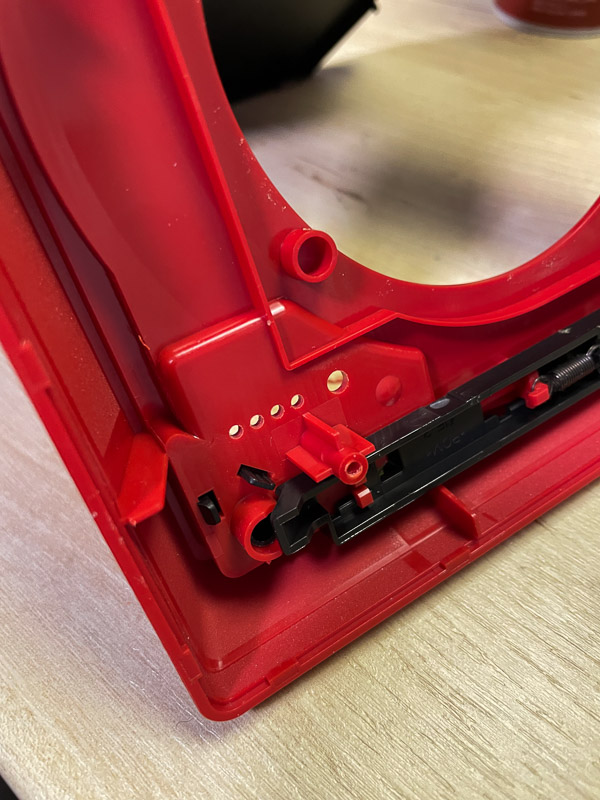
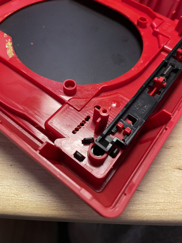
Use crafting knife to widen the cutout.
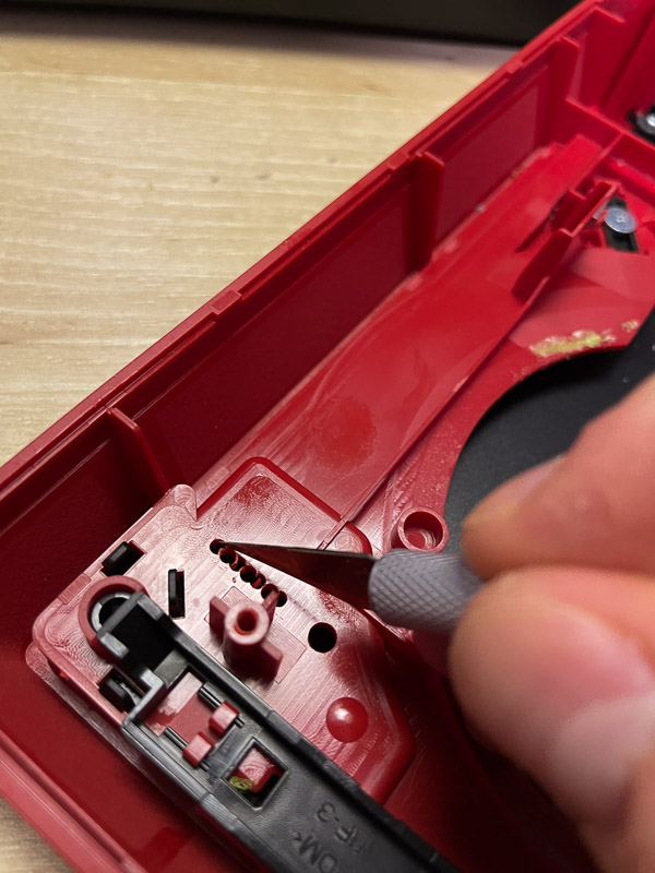
Use small file to finish off the cutout.
The main PCB comes assembled with 3D printed frame. It's mounted on the screw post previously used by the drill guides. Connect other end of flex cable to the main PCB, make sure it's oriented correctly (silver contacts facing top). Reversing the cable may be potentialy dangerous for your console/SDRST kit.
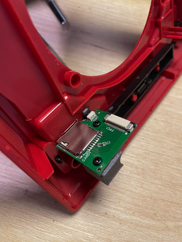
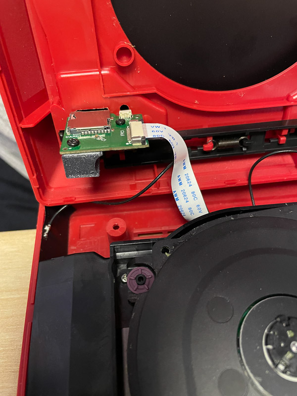
You're done with hardware part. Follow iFixit guide to finish console assembly. You can now proceed with software modification using guides from this wiki.
- 🏠 Home
- Installation steps:
- 📶 BONUS: WiFi card installation
- 🔗 External links: