-
Notifications
You must be signed in to change notification settings - Fork 1
02. electronic board
It's a double sided board, with some SMDs but not the really badly tiny ones :)
Using the provided gerber files you can order boards from any pcb maker, for instance jlcpcb.com will make 5 of them for $2 (plus shipping).
You'll obvisouly need some flux paste to solder them:
- don't breathe the fumes
- cleanup with IPA after soldering is done, because it's corosive.
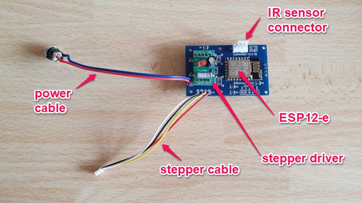
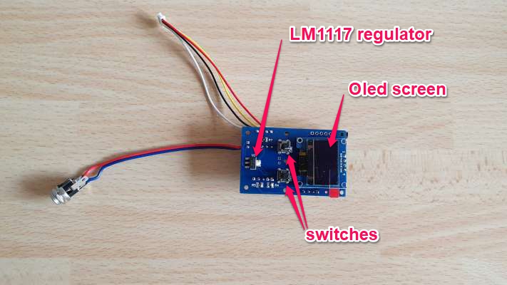
I bought the smallest and cheapest stepper driver I could find on ebay:
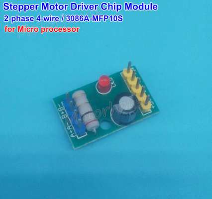
The only problem is that the pins are not oriented downward, you'll have to remove them and solder new ones.
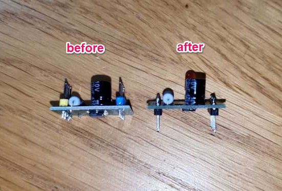
It's a pain to do this if you don't have a desoldering station.
It would be much better to build the driver from scratch on the PCB, but since I don't know much about these components, it would have required more prototyping and testing.
If anyone feels like doing it, please share :)
If you have the equipment, you can program the ESP-12e before soldering it, which has the advantage of testing it too. I've had a bad one, in a batch of 20, you don't want to discover this once it's soldered on a board.
If you don't have the tools, you'll be able to program it onboard. However, do not attempt doing so before soldering all the pullups resistors: it won't work.
On board programming will use the serial interface available on the PCB:
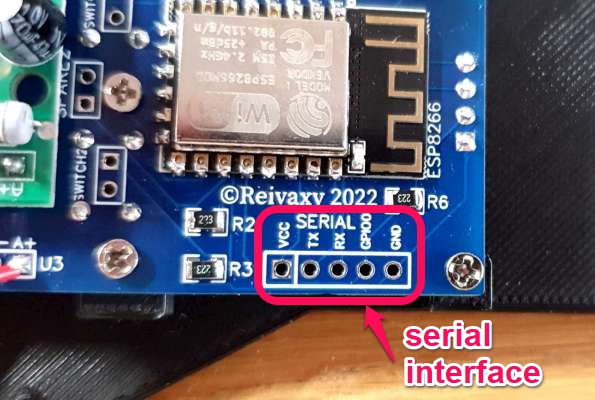
and a "USB to ESP8266 ESP-01 adapter" such as:
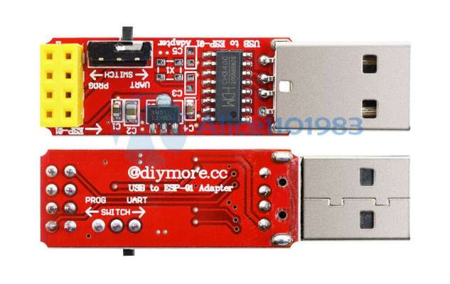
This serial interface will also allow you to upgrade the firmware later, in case you can't use the Wifi firmware upgrade feature.
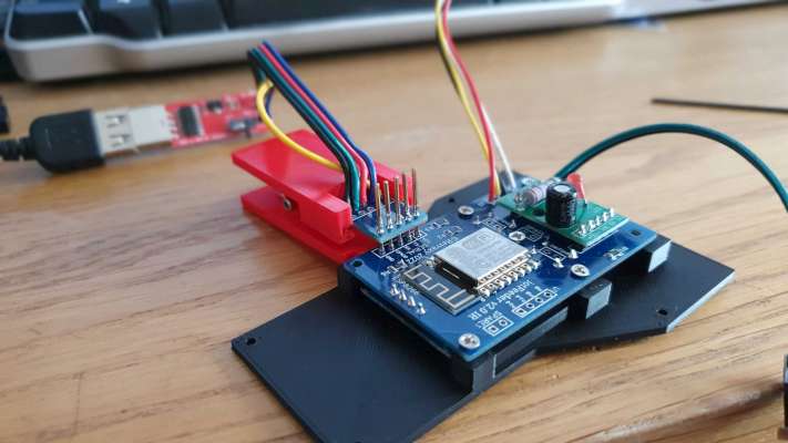
In the 3D file directory you'll find two files to print a clamp to easily use the serial interface.
This is a 0.96" OLED LCD Display I2C 128x64
Be careful:
- there is a 7 pins version (SPI), but you'll need the 4 pins version (I2C).
- Either buy the blue or the white pixel color version, not the blue and yellow. On older projects, I have found out the white version seems to age better.
- be careful with the screen corners, it's very thin glass, and breaking even a corner can break the whole display (speaking from experience...)
- depending on where you buy them, they can come with power pins reversed, and incorrect powering will instantly fry the display :(
It seems like the most common version has pins ordered like this: "GND, VCC, SCL, SDA" which is what I implemented on the PCB
But I also got some with "VCC, GND, SCL, SDA"
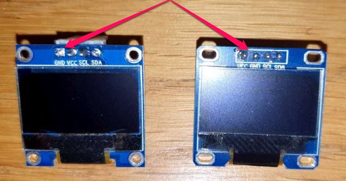
If you ever get the latter, I suggest to replace the two power pins of the straight pin connector that normally connects the oled screen to the iotFeeder board with two tiny wires that allow you to interchange VCC and GND
It's composed of an IR LED, and an IR phototransistor. They must face each other so that the food falling in between will break the IR ray, wich will make the tension change on the phototransistor emitter.
The LED and the phototransistor are each soldered onto a very small and thin (0.6mm thick) PCB.
I have several hundreds of these tiny PCBs, and if you want to build this feeder, I'll send a pair to you free of charge, as a welcome-on-board-this-project gift! Just get in touch to give me your mail address.
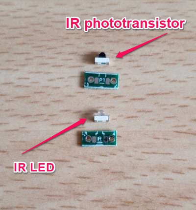
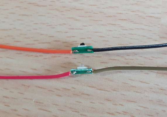
The wires need to be soldered "flat", not traversing the PCB. They are then inserted into the IRInsert 3D printed part:
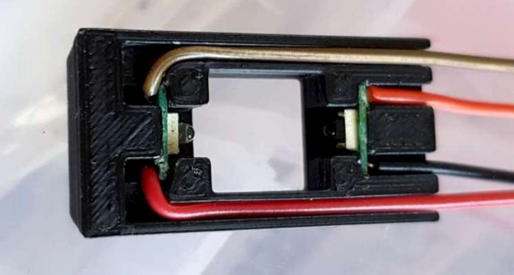
I thought it might be useful to drown each (the LED and the phototransistor) in a big drop of epoxy resin once in place in the IRInsert to protect them from water micro projection, salt, and fish food, but I haven't done it yet. I'll see how this ages in the installed feeders.
Update: one feeder on a saltwater tank was getting water splashes from the fish rushing to feed. As a consequence, some food got wet and clogged the oulet. Humidity crept up the IR detectors, and even the bearing which started to rust. I replaced it and designed a much higher clamp for the whole feeder so that it would not get wet. I tried the epoxy resin and it didn't work well, so I designed a new 3D printed IR tray so that the IR sensors would be protected, but it needs to be printed with translucent filament (or bi color if your printer supports it)
The 4 wires will then need to be inserted in the main case, all the way through:
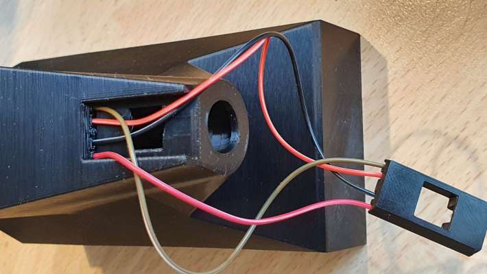
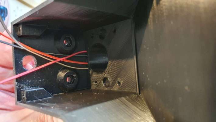
You can then either solder them on the board, or use a connector, which is what I did, and which allows you to easily fully disconnect the board if needed.