-
Notifications
You must be signed in to change notification settings - Fork 426
GL200 Dial board
Function
Variants
Parts
Programming
External interfaces
Service interfaces
Board view
Schematics
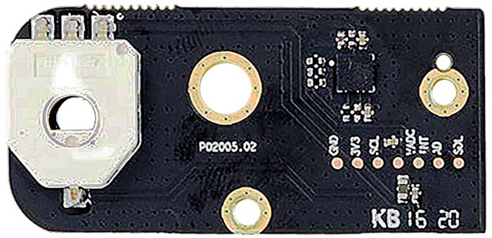
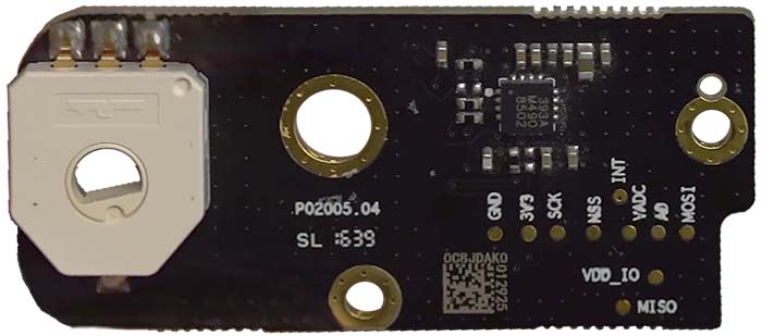
There are two distinct dial boards in each Remote Controller. Each contain not only the dial potentiometer, but also magneto-static sensor for reading control stick position. Having these on a separate board makes any tension applied by user be separated from the fragile main electronics.
Several versions of the boards are known.
| Marking | Overview |
|---|---|
| P02005.02 | The first version. |
| P02005.04 | |
| P02005.06 |
| Marking | Overview |
|---|---|
| P02006.03 | The first version. |
| P02006.05 | |
| P02006.06 |
| Marking | Amt. | Pkg. | Function | Specification |
|---|---|---|---|---|
| TODO |
No programmable components exist on these boards.
| Marking | Overview |
|---|---|
| TODO |
TODO
Top of a P02005.02 board:
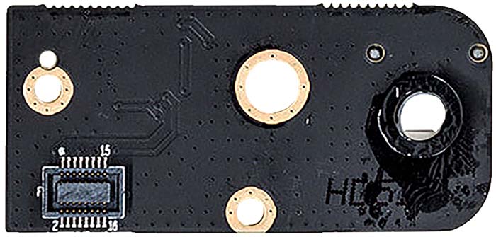
Bottom of the P02005.02 board:
Top of a P02005.04 board:
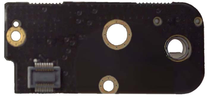
Bottom of the P02005.04 board:
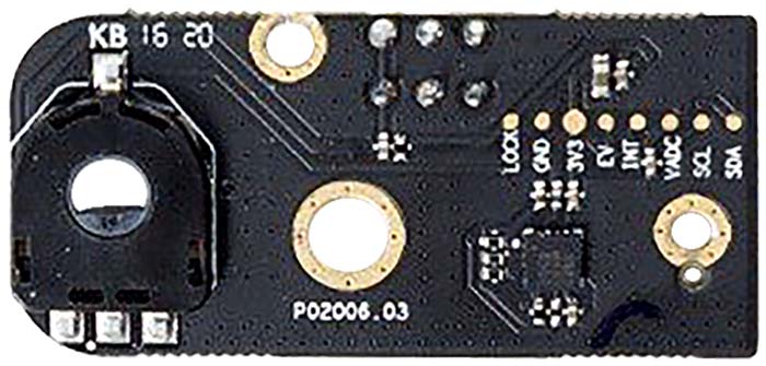
Top of a P02006.03 board:
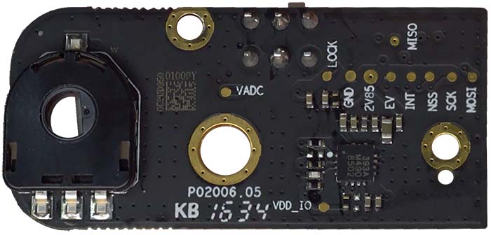
Top of a P02006.05 board:
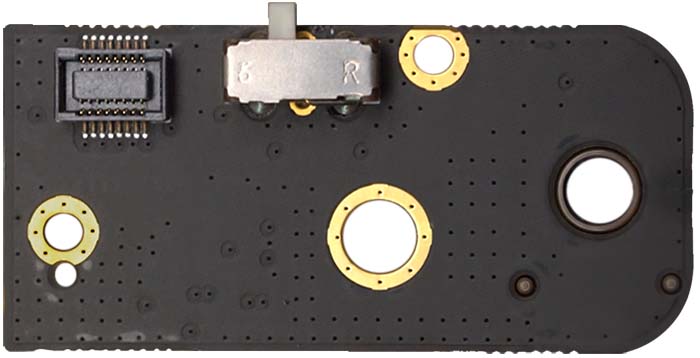
Bottom of the P02006.05 board:
No schematics available.
This page is created by drone enthusiasts for drone enthusiasts.
If you see a mistake, or you know more about specific subject, or you see an area for improvement for the wiki - create an issue in this project and attach your patch (or describe the change you propose).
