-
Notifications
You must be signed in to change notification settings - Fork 427
WM330 Flight Controller board
Function
Variants
Parts
Programming
External interfaces
Service interfaces
Board view
Schematics
Flight controller board is soldered at the top of a damper board, and has Inertial Measurement Unit and barometer soldered on it as well. The damper board reduces vibration the IMU and barometer receives, and provides sockets for Flat Film Wire cables which connects it to ESC boards and 3-in-1 board.
Flight Controller CPU runs Real-Time Operating System which acquires readings from all sensors and sends control signals to motors ESC units.
IMU precision is improved by using 2 chips, put on the board in different orientations. The board has cutouts around the IMU chips, which are also covered by silicon. This helps with accurately measuring acceleration by nullifying stress caused by mass of the board.
The known variants are listed below.
| Marking | Overview |
|---|---|
| P01551.06 | FC Core board first version. |
| P01419.5 | FC Damper and Connectors board first version. |
| P01551.10 | FC Core board. |
| P01419.7 | FC Damper and Connectors board. |
| Marking | Amt. | Pkg. | Function | Specification |
|---|---|---|---|---|
| MP66 | 2 | QFN-24 | Inertial measurement unit; MPU-6600 QFN Accelerometer gyroscope sensor | mp65 description |
| STM32F427? | 1 | ARM Cortex-M4 core with DSP and FPU, 2 Mbytes Flash, 180 MHz CPU, ART Accelerator, Chrom-ART Accelerator, FMC with SDRAM | description | |
| MEAS M????? 5607?? | 1 | QFN-8 | MS5607 barometer/pressure sensor | |
| PA 6EA | 1 | 3x3 UDFN/WSON | Mini Linear Regultor; part used is DI AP7361ADJ, but it could also be TI TPS7A16 | DI datasheet TI description |
| Chips | Firmware | Description |
|---|---|---|
| STM32F | m0305, m0306 | Flight controller (MC) programming, loader(05) and application(06). |
The board contains one connector:
| Marking | Overview |
|---|---|
| ESC A | 12-pin Flat Film Wire connector |
| ESC B | 35-pin Flat Film Wire connector |
| 3IN1 | 31-pin Flat Film Wire connector |
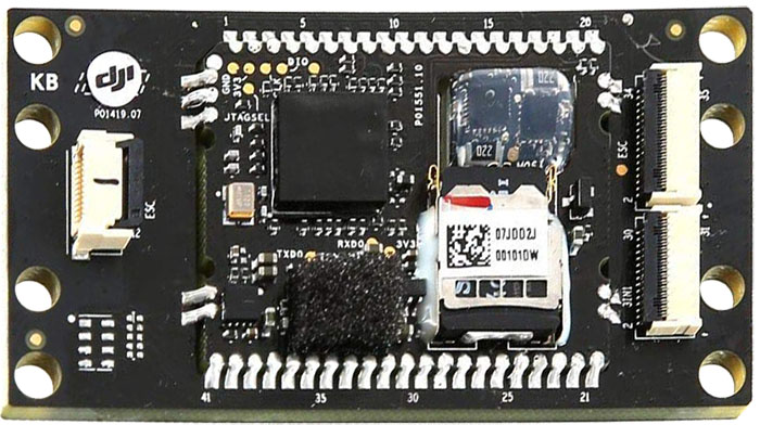
The following service pads exist on this board:
| Marking | Overview |
|---|---|
| GND | |
| 3V3 | |
| JTAGSEL | |
| CLK | |
| DIO | |
| ERASE | |
| TXDO | |
| RXDO | |
| 3V3 | |
| MISO | |
| SCK | |
| CAN1_T | |
| CAN1_R | |
| SCK_MAM | |
| TEST | |
| RST | |
| GND | |
| 5V | |
| SS | |
| MISO | |
| MOSI | |
| VCC3V6 | |
| GND |
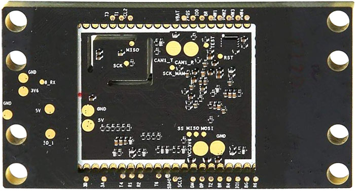
The following service pads exist on this board:
| Marking | Overview |
|---|---|
| GND | |
| 3V6 | |
| 5V | |
| B_RX | |
| IO_1 | |
| T3 | |
| T1 | |
| SCL2 | |
| VBAT | |
| SDA2 | |
| IOO | |
| BR | |
| PWM1 | |
| PWM2 | |
| PWM3 | |
| PWM4 | |
| 3D | |
| 3A | |
| T4 | |
| R1 | |
| R2 | |
| T6 | |
| SDA0 | |
| SCL0 | |
| DM | |
| DP | |
| T2 | |
| BR | |
| R4 | |
| IO1 | |
| BG | |
| R6 |
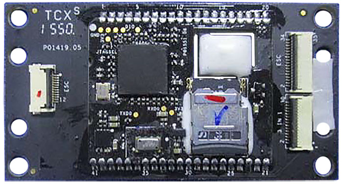
Top of a P01551.06 board on P01419.5 board:
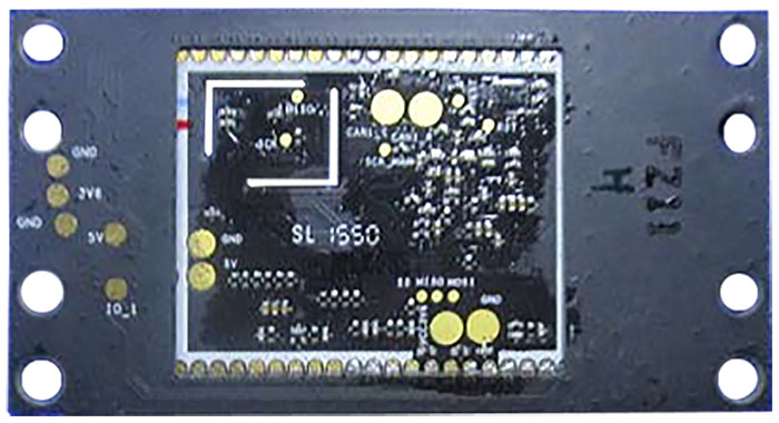
Bottom of the P01551.06 board on P01419.5 board:
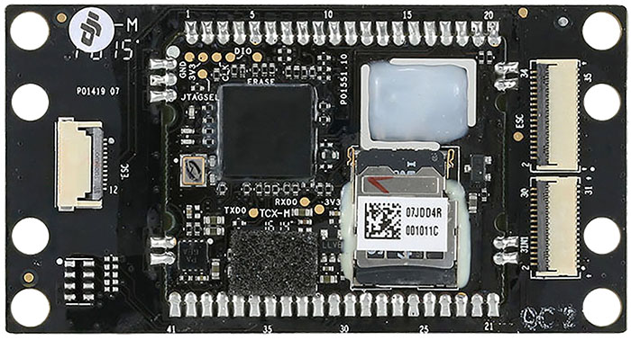
Top of a P01551.10 board on P01419.7 board:
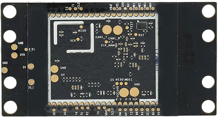
Bottom of the P01551.10 board on P01419.7 board:
Top of another P01551.10 board on P01419.7 board:
Bottom of the P01551.10 board on P01419.7 board:
No schematics available.
This page is created by drone enthusiasts for drone enthusiasts.
If you see a mistake, or you know more about specific subject, or you see an area for improvement for the wiki - create an issue in this project and attach your patch (or describe the change you propose).
