-
Notifications
You must be signed in to change notification settings - Fork 426
P330Z Center board
Function
Variants
Parts
Programming
External interfaces
Service interfaces
Board view
Schematics
The Center board delivers power to all components of the drone and acts as a hub for connecting all modules to Flight Controller. The Flight Controller module is mounted on the Center Board.
There are multiple versions of the board.
| Marking | Overview |
|---|---|
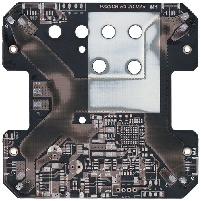
| P330CB-H3-2D V2 |
| Marking | Amt. | Pkg. | Function | Specification |
|---|---|---|---|---|
| TODO | 1 |
| Chips | Firmware | Description |
|---|---|---|
| TODO |
Connectors on the board are:
| Marking | Overview |
|---|---|
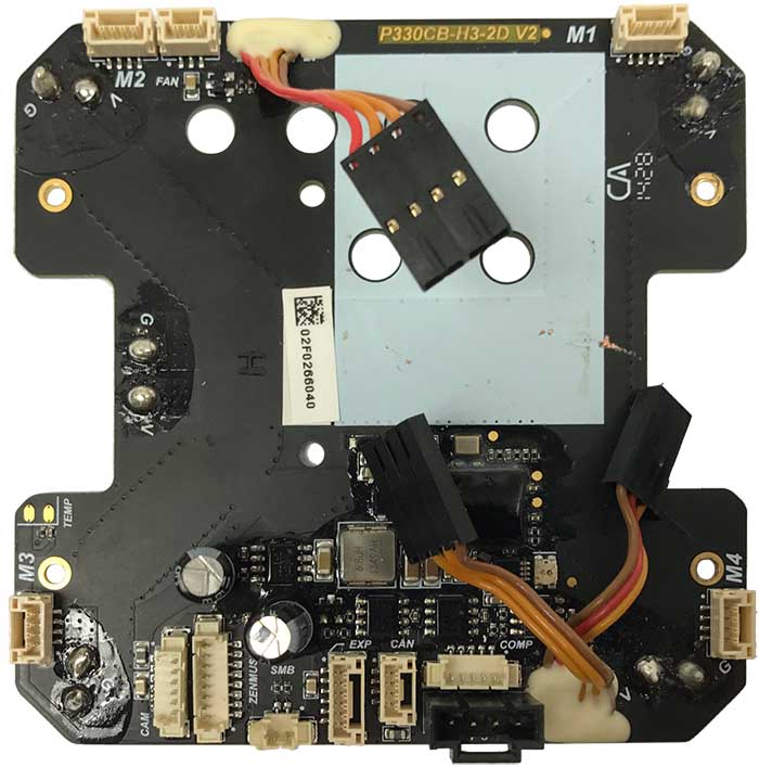
| M1,M2,M3,M4 | 4-pin socket to ESC; JST GHR-xxV-S Series |
| FAN | 3-pin socket; JST GHR-xxV-S Series |
| CAN | 4-pin socket; JST GHR-xxV-S Series; fitting plug Molex Micro-Fit 3.0 43640 - 43645 |
| EXP | 6-pin socket; JST GHR-xxV-S Series |
| SMB | 2-pin socket; Molex PicoBlade 51021 |
| COMP | 5-pin socket; Molex PicoBlade 51021 |
| CAM | 6-pin socket; Molex PicoBlade 51021 |
| ZENMUSE | 8-pin socket; Molex PicoBlade 51021 |
| Mx-V,Mx-G | High current pads, for each arm |
| BAT-V,BAT-G | High current pads for battery connector |
| GPS | 4-pin pads; for soldering in GPS |
| TEMP | 2-pin pads |
| G,V,B | 3-pin pads |
| N,R,T,G | 4-pin pads |
The following service pads exist on this board:
| Marking | Overview |
|---|---|
| TODO |
Top of a P330CB-H3-2D V2 board:
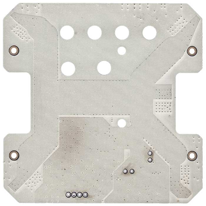
Bottom of the P330CB-H3-2D V2 board:
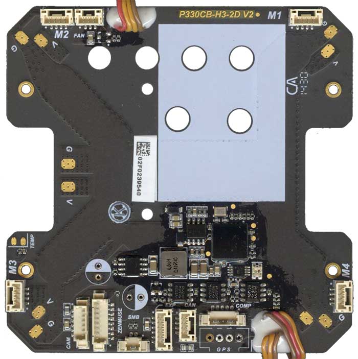
The same top board with some components desoldered:
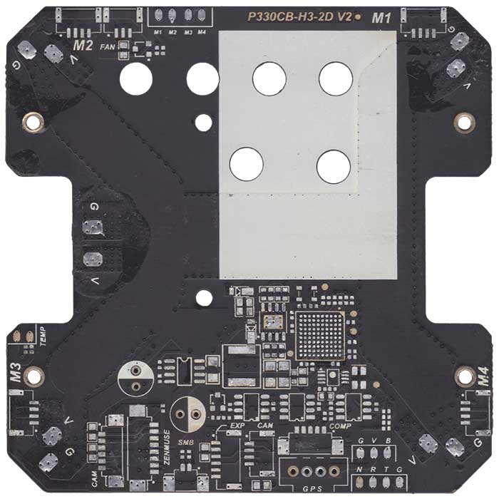
The same top board again, with all components gone:
And last picture of that board, now with copper traces exposed:
Photos of the board with desoldered components come from an RC-groups thread.
Schematic is available in RC-groups thread.
This page is created by drone enthusiasts for drone enthusiasts.
If you see a mistake, or you know more about specific subject, or you see an area for improvement for the wiki - create an issue in this project and attach your patch (or describe the change you propose).
