-
Notifications
You must be signed in to change notification settings - Fork 1
The navigation stack in ROS
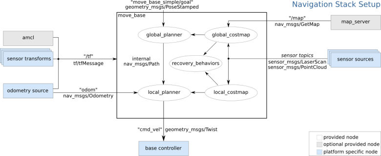
The navigation stack in ROS is a 2D navigation stack that uses information from odometry, sensor streams and a goal pose to output safe velocity commands to a mobile base for navigation purposes.
A pre-requisite for using the navigation stack is that the robot is running ROS, has a tf transform tree and publish sensor data using the correct ROS message types. The navigation stack also needs to be configured for the shape and dynamics of a robot to perform at a high level.

At an abstract level, a transform tree defines the offsets in terms of translation and rotation between different coordinate frames. For the TB3 the LIDAR and the moving base center point are offset. To navigate properly an offset must be defined for the LIDAR and the moving base coordinate frames.
By using tf transform trees it is possible to manage the transformation between coordinate frames. To define and store the relationship between the LIDAR and the moving base, they have to be added to a transform tree. On a conceptual level, each node in the transform tree corresponds to a coordinate frame and each edge corresponds to the transformation that needs to be applied to move from the current node to its child.
After setting up a transform tree it is as simple as making a call to the tf library to convert the LIDAR scan to be relative to the moving base instead of the LIDAR scanner.
A brief tutorial of how to set up a broadcaster/listener program was found here.
While the TB3 is quite simple in its design it is still a lot of work to publish all these frames to the tf library. The robot state publisher tool is a tool that can solve this problem.
The robot state publisher is a tool for broadcasting the state of the robot to the tf transform library. It can be used as a standalone ROS node or as a library.
As recommended by the documentation, the aim was decided to be to use the robot state publisher as a ROS node.
This required a URDF loaded onto the parameter server and a source that publishes the joint positions as a sensor_msgs/JointState topic. A very brief tutorial on how to use the robot state publisher tool as a node can be found here.
The URDF that was the same as created earlier for simulating the TB3 in Gazebo.
A method for specifying what state the robot in was necessary for the robot state publisher to correctly update the transform of the initial robot state. The dynamics of the robot would be defined in a state publisher file. The file would contain the joints that were updated, the transforms, the publishing of these and the clamping of the related variables.
The navigation stack used information from sensors to avoid obstacles in the world. It assumed there were some form of laser scan or point cloud being published by the robot. In the case of the TB3, this was the LIDAR and further on, a depth camera. This task was solved by the Computer Vision team. Their work can be found here.
The navigation stack required that odometry information was published by using tf and sending odometry messages that contain velocity information. There was a tutorial detailing the specifics around this task.
The odometry message stored an estimate of the position and the velocity of a robot in free space. The pose in the message corresponded to the estimated position of the robot in the odometric frame along with optional statistical information about the certainty of the pose estimate. The message contains twist information and is corresponded to the velocity of the robot in the child frame. Normally this is the mobile base.
tf also needed to know the odometry information to correctly manage the relationships between frames. So a publishment of this information was also necessary.
The map server provided a map data for the navigation stack as a service. The format of the maps consisted of a YAML file that described the meta-data and name of the image file while the image file encoded the occupancy data.
The image described the occupancy state of each cell of the world by colouring them according to a configuration. The standard configuration assumed whiter pixels were free, blacker pixels occupied and pixels in between were unknown.
Image data was read via SDL_Image which supported most popular image formats. Not PNG, however.
The YAML format had six required fields:
- image: Path to the image file containing the occupancy data
- resolution: Resolution of the map, meters/pixel
- origin: The 2D pose of the lower-left pixel in the map
- occupied_thresh: Pixels with occupancy probability greater than the threshold were considered completely occupied.
- free_thresh: Pixels with occupancy probability less than this threshold were considered completely free
- negate: Wether the white/black free/occupied semantics should be reversed (Note:
negate = Falsewould mean that black(0)had the highest value(1.0)and white(255), the lowest value(0.0).).
It also had one optional parameter:
- mode: Could have one of three values: trinary, scale or raw. Trinary was the default. This would change the value interpretation depending on the mode chosen.
The three modes differed in the way they interpreted occupancy.
- Trinary divided the output into three categories; occupied, free and unknown.
- Scale tweaked the trinary method to allow for more output values than trinary. It instead outputted a full gradient of values ranging from [0, 100].
- Raw mode outputted
xfor each pixel, so output values were [0, 255].